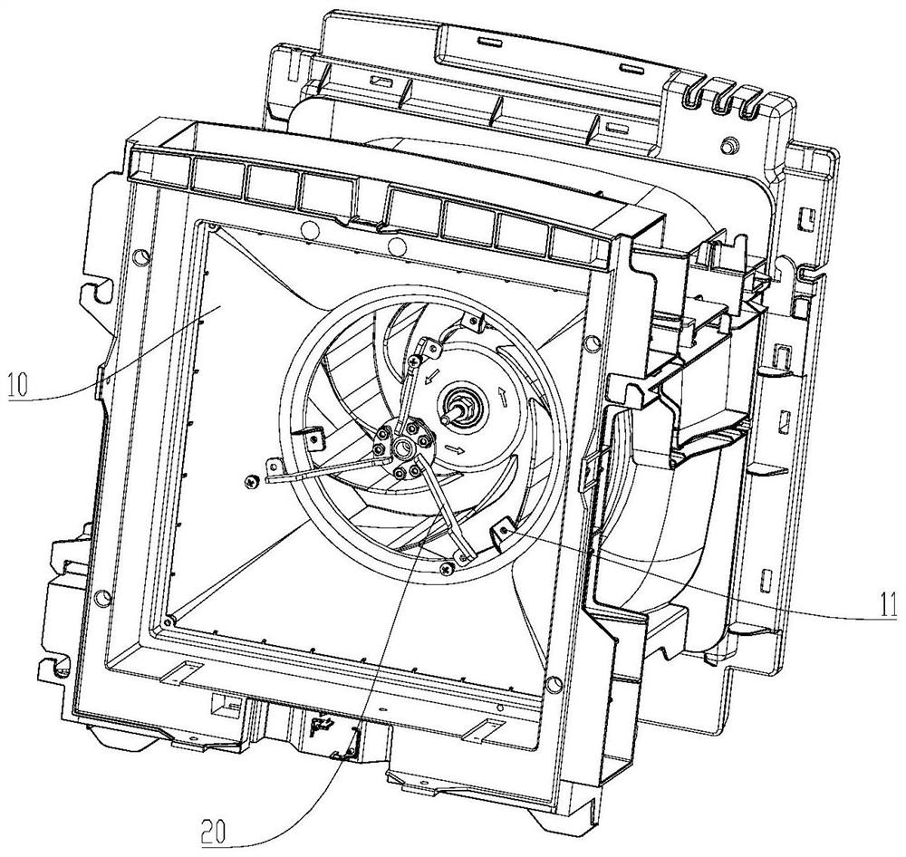
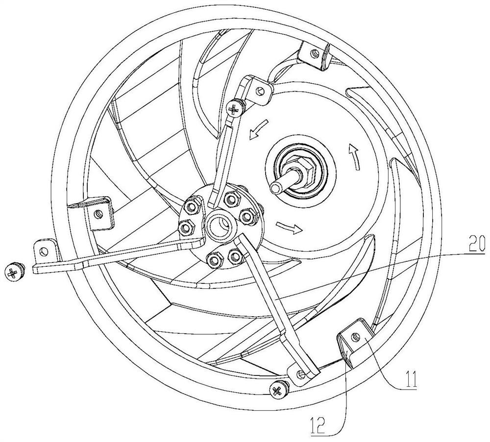
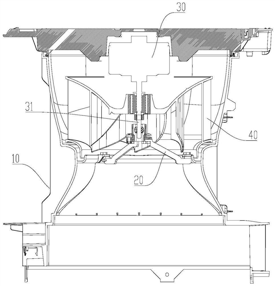
Motor mounting frame, fan assembly and air purifier

A motor mounting frame and fan technology, applied in electric components, electromechanical devices, electrical components, etc., can solve problems such as wind wheel friction, achieve stable installation, reduce the number of brackets, and ensure assembly accuracy

Pending Publication Date: 2020-11-06
GREE ELECTRIC APPLIANCES INC
View PDF0 Cites 0 Cited by
  • Summary
  • Abstract
  • Description
  • Claims
  • Application Information

AI Technical Summary

Problems solved by technology

[0004] The technical problem to be solved by the present invention is to overcome the defects in the prior art that the motor shakes easily to cause friction of the wind wheel, thereby providing a fan assembly that reduces the shake of the motor and thus reduces the friction of the wind wheel
[0005] Anot

Method used


Image

  • Motor mounting frame, fan assembly and air purifier
  • Motor mounting frame, fan assembly and air purifier
  • Motor mounting frame, fan assembly and air purifier

Examples


Example Embodiment

[0056] Example 1

[0057] combine Figure 5-Figure 8 As shown, the motor mounting frame provided in this embodiment includes:

[0058] the shaft sleeve 21, a through hole 211 is formed in its interior;

[0059] The bearing 24 is directly or indirectly assembled and connected to the shaft sleeve 21, and a positioning shaft hole 241 is formed inside the bearing 24 in a direction parallel to the axis of the through hole;

[0060] At least part of the outer edge of the shaft sleeve 21 is provided with a shaft sleeve flange 212 , and a fixing position 214 is formed on the shaft sleeve flange 212 .

[0061] Preferably, the shaft sleeve 21 is configured as a cylindrical structure, and the through hole 211 is hollowly formed in its interior along the axial direction. Preferably, the shaft sleeve 21 is configured as a thin-walled structure.

[0062] Preferably, the sleeve flange 212 extends in the radial direction along the outer surface of the sleeve 21, and the sleeve flange 212 ...

Example Embodiment

[0092] Embodiment 2

[0093] combine Figure 9 As shown, this embodiment is a deformation structure of the motor mounting bracket provided in the above-mentioned first embodiment. The difference from the above-mentioned embodiment is that the L-shaped bending structure is cancelled at both ends of the bracket 22, and the two ends of the extension part 222 The flanges are added to strengthen the structural strength of the bracket 22 .

[0094] Preferably, the flanges are located on the same side of the plane where the extension portion 222 is located.

Example Embodiment

[0095] Embodiment 3

[0096] combine Figure 10 As shown, this embodiment is a modified structure of the motor mounting bracket provided in the above-mentioned first embodiment. The difference from the above-mentioned embodiment is that the extension portion 222 of the bracket 22 is configured as a plate-like structure, and the extension portion 222 is a plate-like structure. The plane where the structure is located is perpendicular to the axial direction of the through hole 211 .

[0097] Preferably, flanges are formed on both side edges of the plate-like structure of the extension portion 222 along the width direction, so as to increase the structural strength of the bracket 22 .

[0098] Preferably, ventilation holes are formed on the plate-like structure of the extension portion 222 to reduce wind resistance.


PUM


Abstract

The invention relates to the technical field of motor damping, in particular to a motor mounting frame, a fan assembly and an air purifier. The motor mounting frame comprises a shaft sleeve and a bearing. A through hole is formed in the shaft sleeve. The bearing is directly or indirectly in assembly connection with the shaft sleeve. A positioning shaft hole is formed in the bearing and is parallelto the axis direction of the through hole. A shaft sleeve convex edge is arranged along at least part of an outer edge of the shaft sleeve. Fixed positions are formed on the shaft sleeve convex edges. The motor mounting frame provided by the invention is provided with the shaft sleeve convex edge along at least part of the outer edge of the shaft sleeve, and the fixed positions are formed on theshaft sleeve convex edge, so that the motor mounting frame can be fixed through the fixed positions. A motor shaft is convenient to rotate in the motor mounting frame according to the specific axis without relative shaking when the motor mounting frame is fixed, and the smooth and steady operation of a motor is ensured.

Description

technical field [0001] The invention relates to the technical field of motor shock absorption, in particular to a motor mounting frame, a fan assembly and an air purifier. Background technique [0002] In the prior art, the air purifier usually adopts the form in which the motor and the wind wheel are placed vertically. In order to effectively reduce vibration and noise, the main body of the motor is usually fixed on one side, and shock-absorbing rubber is installed on the upper and lower ends of the motor housing. Pad, this kind of setting form, during the long-term high-speed operation of the motor, the rubber pad is constantly worn due to vibration, the motor shakes and the eccentricity of the wind wheel increases, causing the wind wheel to rub against the volute and generate noise. On the other hand, due to installation requirements, when the motor and the wind wheel need to be installed horizontally, the wind wheel and the motor are placed horizontally. The wind wheel i...

Claims


Application Information

Patent Timeline
IPC IPC(8): F24F3/16F24F13/24H02K5/00H02K5/24H02K7/00H02K7/14
CPCF24F3/16F24F13/24F24F2013/247H02K5/00H02K5/24H02K7/003H02K7/14
Inventor 钟继鑫杨晓光李曙光
Owner GREE ELECTRIC APPLIANCES INC
Why Eureka
Try Eureka