
A continuous zoom optical system with fast image motion compensation capability

An image movement compensation and optical system technology, applied in the field of continuous zoom optical systems, can solve the problems of difficulty in taking into account the search and detailed inspection functions of large and small fields of view, inability to effectively compensate for high-speed image movement, and large component inertia, and achieve uniform relative illuminance distribution. , Reduce the difficulty of optical debugging, the effect of small system size

Active Publication Date: 2021-07-27
XI'AN INST OF OPTICS & FINE MECHANICS - CHINESE ACAD OF SCI
View PDF7 Cites 0 Cited by
  • Summary
  • Abstract
  • Description
  • Claims
  • Application Information

AI Technical Summary

Problems solved by technology

[0009] In order to solve the problem of low compensation ability, poor reliability, or large component inertia, the existing technology cannot achieve effective compensation for high-speed image motion, and the resolution of the area scan zoom imaging system working in the mid- and long-wave infrared spectrum is low. Since the area array scanning equipment in the visible spectrum is mostly a fixed-focus system, it is difficult to take into account the technical problems of the search and detailed search function of the large and small fields of view. The present invention provides a continuous zoom optical system with fast image motion compensation capability

Method used


Image

  • A continuous zoom optical system with fast image motion compensation capability
  • A continuous zoom optical system with fast image motion compensation capability
  • A continuous zoom optical system with fast image motion compensation capability

Examples


Embodiment Construction

[0093] The content of the present invention will be further described in detail below in conjunction with the accompanying drawings and specific embodiments.

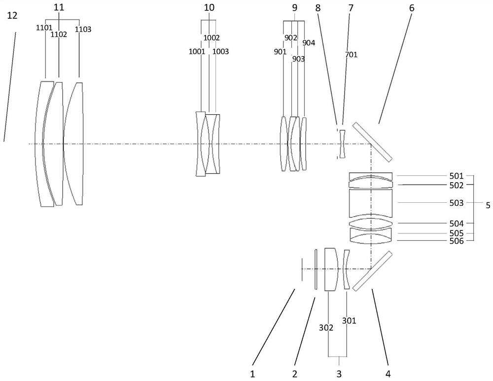
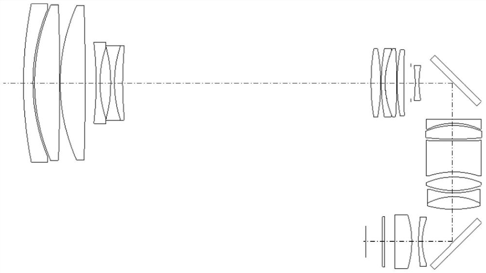
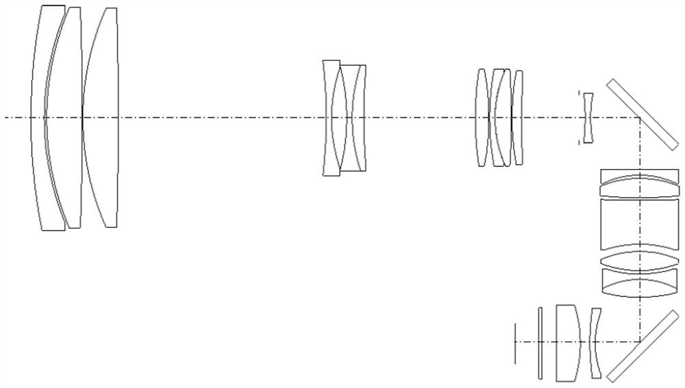
[0094] Such as figure 1 As shown, a continuous zoom optical system with fast image motion compensation capability includes a front fixed mirror group 11, a variable power mirror group 10, a compensation mirror group 9, Diaphragm 8, middle fixed mirror group 7, first folding mirror 6, relay mirror group 5, second folding mirror 4, rear fixed mirror group 3 and filter 2; front fixed mirror group 11 on the object side It is the object plane 12 of the continuous zoom optical system, and the image side of the optical filter 2 is the focal plane 1 of the continuous zoom optical system; the front fixed lens group 11, the zoom lens group 10, the compensation lens group 9, the diaphragm 8, the middle The central axes of the fixed mirror group 7, the relay mirror group 5, the rear fixed mirror group 3 and the optical filter 2 ar...


PUM


Abstract

The present invention provides a continuous zoom optical system capable of fast image motion compensation, which solves the problems in the prior art that the resolution of the imaging system is low, it is difficult to take into account the search functions of large and small fields of view, and it is impossible to realize effective compensation for high-speed image motion. The system includes a front fixed mirror group, a variable power mirror group, a compensation mirror group, a diaphragm, a fifth negative lens, a first folding mirror, a relay mirror group, and a second folding mirror arranged in sequence from the object plane to the focal plane. , rear fixed lens group and filter; the front fixed lens group includes the first negative lens, the first positive lens and the second positive lens; the zoom lens group includes the second negative lens and the first cemented lens group; the compensation lens group includes The fourth positive lens, the second cemented lens group and the sixth positive lens; the relay lens group includes the sixth negative lens, the seventh positive lens, the seventh negative lens, the eighth positive lens and the third cemented lens group; the rear fixed mirror The group includes the ninth negative lens and the tenth positive lens; the zoom lens group and the compensation lens group can move linearly back and forth along the optical axis to realize continuous zooming.

Description

technical field [0001] The invention belongs to the field of photoelectric technology and relates to a continuous zoom optical system, in particular to a continuous zoom optical system with fast image motion compensation capability. Background technique [0002] In recent years, the scanning area array detection and imaging system has developed rapidly in response to application requirements such as aerial remote sensing and peripheral vision early warning. Among them, with continuous zoom function, it can realize area scan imaging of large field of view search and small field of view detailed inspection The system gets focused attention. This type of imaging system requires the photoelectric platform to scan and image in azimuth 360° or within a specific angle range at a certain speed, and perform gaze tracking for a specific target area. However, due to the relative motion between the focal plane and the scene of the area array detector within the integration time, result...

Claims


Application Information

Patent Timeline
Patent Type & Authority Patents(China)
IPC IPC(8): G02B15/15G02B15/14
CPCG02B15/15G02B15/145
Inventor 曲锐梅超陈卫宁杨洪涛
Owner XI'AN INST OF OPTICS & FINE MECHANICS - CHINESE ACAD OF SCI
Learn More