
Internet of Things electronic tag with power grid topological structure recognition function

A technology of structure identification and power grid topology, applied in the field of wireless communication, can solve the problems of difficult to observe accurately, mutual interference of antennas, reduce the reliability of the overall structure, etc., to achieve the effect of easy installation and reduced volume

Pending Publication Date: 2020-11-06
CHINA ELECTRIC POWER RES INST
View PDF6 Cites 0 Cited by
  • Summary
  • Abstract
  • Description
  • Claims
  • Application Information

AI Technical Summary

Problems solved by technology

Generally speaking, limited to the size of the tag itself, after the battery is exhausted, the tag needs to be removed and replaced manually. The operation is cumbersome, and it also increases the complexity of the tag structure design and reduces the reliability of the overall structure. To overcome the above problems, There are electronic tags capable of wireless charging, and the battery in the electronic tag is charged by wireless charging, but this is easy to cause multiple antennas in the electronic tag at the same time, and various antennas are likely to cause mutual interference, resulting in charging or communication. Efficiency drops
[0005] At the same time, due to the many types of power grid topology, it is difficult to achieve accurate observation through a single device
With the construction and development of the power grid, when the grid structure changes, it is difficult to update the grid structure information in time, which brings great difficulties to the operation and maintenance work

Method used


Image

  • Internet of Things electronic tag with power grid topological structure recognition function
  • Internet of Things electronic tag with power grid topological structure recognition function
  • Internet of Things electronic tag with power grid topological structure recognition function

Examples


Embodiment Construction

[0024] In order to better understand the present invention, the content of the present invention will be further described below in conjunction with the accompanying drawings and examples.

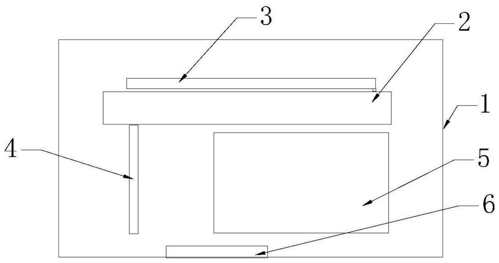
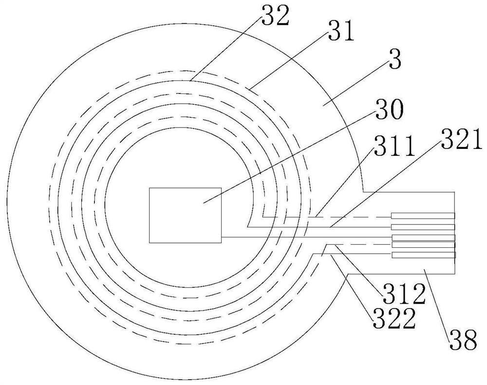
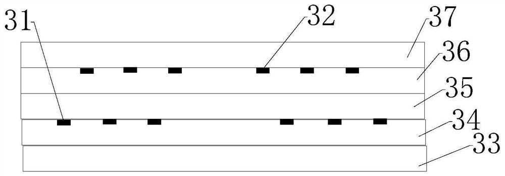
[0025] The Internet of Things electronic tag includes a flexible shell 1, a main board 2, a first flexible circuit board 3, a second flexible circuit board 4, a rechargeable battery 5, and a temperature sensor 6. A flexible display device can also be set on the flexible shell 1, For displaying the remaining power of the rechargeable battery, the main board 2 is mainly provided with an embedded processor MCU, and the first flexible circuit board 3 is arranged with a Qi antenna 31 (wireless charging antenna) and an RFID antenna 32, and the second flexible circuit board 3 A narrowband Internet of Things (NB-IoT) antenna 41 is arranged on the circuit board 4, the first flexible circuit board 3 is arranged above the main board 2, and is arranged parallel to the main board 2, and the second flexi...


PUM


Abstract

The invention discloses an Internet of Things electronic tag with a power grid topological structure recognition function. Which comprises flexible shell, mainboard and first flexible circuit board, second flexible circuit board, rechargeable battery, temperature sensor, the mainboard is provided with an embedded processor MCU and a large-capacity storage unit. A Qi antenna and an RFID antenna arearranged on the first flexible circuit board; a narrowband Internet of Things antenna is arranged on the second flexible circuit board; the first flexible circuit board is arranged above the mainboard; wherein the shell is parallel to the main board, the second flexible circuit board and the rechargeable battery are arranged below the main board; the second flexible circuit board is perpendicularto the mainboard; the Qi antenna is arranged on the lower side of the first flexible circuit board; the RFID antenna is arranged on the upper side of the first flexible circuit board; the Qi antennaand the RFID antenna are mutually nested in the vertical direction; the Internet of Things electronic tag is integrally flexible, is convenient to install with curved surface shells of various devices, stores device information through the large-capacity storage unit and reports the device information, realizes recognition of different devices in a line, and can limit interference between antennasof the electronic tag to a great extent at the same time.

Description

technical field [0001] The present invention relates to the field of wireless communication, and more specifically, relates to an electronic label for the Internet of Things including functions such as RFID, narrowband Internet of Things communication, asset status monitoring, and wireless charging. Background technique [0002] The traditional Internet of Things technology uses a unique EPC (Electronic Article Code) code for the item, and writes the code into the electronic tag, identifies the electronic tag on the item through the electronic tag reading and writing equipment, and collects the information of the item into the information system. At the same time, in order to meet the monitoring needs of various equipment, it is necessary to perceive the environmental data of the equipment and the operating status of the equipment in real time. However, at present, all kinds of monitoring devices are isolated, and it is difficult to realize real-time identification and eval...

Claims


Application Information

Patent Timeline
Patent Type & Authority Applications(China)
IPC IPC(8): G06K17/00G06K19/077
CPCG06K17/0029G06K19/07749G06K19/0772
Inventor 仝杰张明皓蒲天骄张树华雷煜卿
Owner CHINA ELECTRIC POWER RES INST
Learn More