
Drive device, electric vehicle, and drive device control method

A driving device and a technology of the control unit, which is applied in the direction of AC motor control, control systems, electrical components, etc., and can solve problems such as the deviation of the installation position of the angle sensor without consideration

Pending Publication Date: 2020-11-06
SHINDENGEN ELECTRIC MFG CO LTD +1
View PDF6 Cites 0 Cited by
  • Summary
  • Abstract
  • Description
  • Claims
  • Application Information

AI Technical Summary

Problems solved by technology

However, since the technology disclosed in this Japanese Patent Laid-Open No. 2002-186274 does not take into account the deviation of the installation position of the angle sensor, this technology is completely irrelevant to the present invention.

Method used


Image

  • Drive device, electric vehicle, and drive device control method
  • Drive device, electric vehicle, and drive device control method
  • Drive device, electric vehicle, and drive device control method

Examples


no. 1 approach

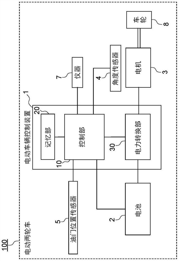
[0113] First, refer to figure 1 An electric two-wheeled vehicle 100 according to the first embodiment as an example of an electric vehicle will be described.

[0114] The electric two-wheeled vehicle 100 is an electric two-wheeled vehicle such as an electric motorcycle that travels by driving a motor using electric power supplied from a battery. Specifically, the electric two-wheeled vehicle 100 is a clutchless electric two-wheeled vehicle in which a motor and wheels are mechanically connected without a clutch.

[0115] Electric two-wheeled vehicles 100 such as figure 1 As shown, it includes an electric vehicle control device 1 as an example of a driving device, a battery 2 , a motor 3 , an angle sensor 4 as an example of a rotation speed detection unit, an accelerator position sensor 5 , an instrument 7 , and wheels 8 .

[0116] Next, each component of the electric motorcycle 100 will be described in detail.

[0117] The electric vehicle control device 1 is a device that c...

no. 2 approach

[0211] Next, a second embodiment in which the energization method is selected according to the running state will be described.

[0212] In the second embodiment, in the third case where the detection speed other than the configuration of the first embodiment is slower than the first reference speed, and the set duty ratio is greater than or equal to the first reference duty ratio, the control unit 10. While turning off the second semiconductor switch Q2, the on / off switching control of the first semiconductor switch Q1 is performed by the U-phase high-side PWM signal (ie, the first-phase high-side PWM signal) with a set duty ratio.

[0213] In addition, when in the third situation, the control unit 10 turns off the fourth semiconductor switch Q4, while passing the V-phase high-side PWM signal (that is, the second-phase high-side PWM signal) with a set duty ratio to the third semiconductor switch Q3. ON / OFF switching control.

[0214] In addition, when in the third situation,...


PUM


Abstract

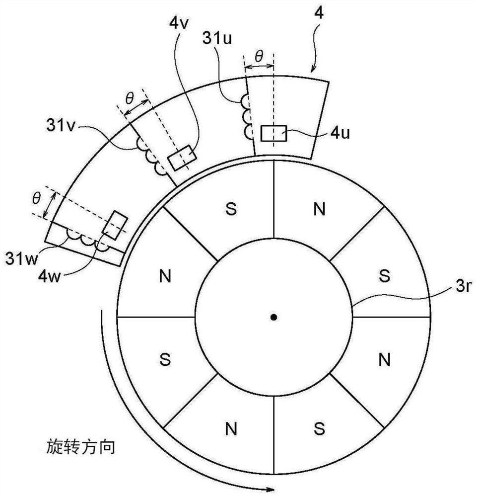
This drive device is provided with a control unit for controlling the drive of a motor by controlling first to sixth switches. The control unit periodically sets continuous first to sixth energizationperiods, each of which corresponds to an electrical angle of 60 degrees, in accordance with first to sixth detection periods. The control unit PWM-controls the first to sixth switches so as to switchbetween 120 degree-energization for flowing phase current during continuous two energization periods among the first to sixth energization periods and 180 degree-energization for flowing phase current during continuous three energization periods among the first to sixth energization periods. The control unit sets an energization period during switching among the first to sixth energization periods such that the energization period is shifted by a period in accordance with the arrangement angle of an angle sensor with respect to a detection period during switching among the first to sixth detection periods.

Description

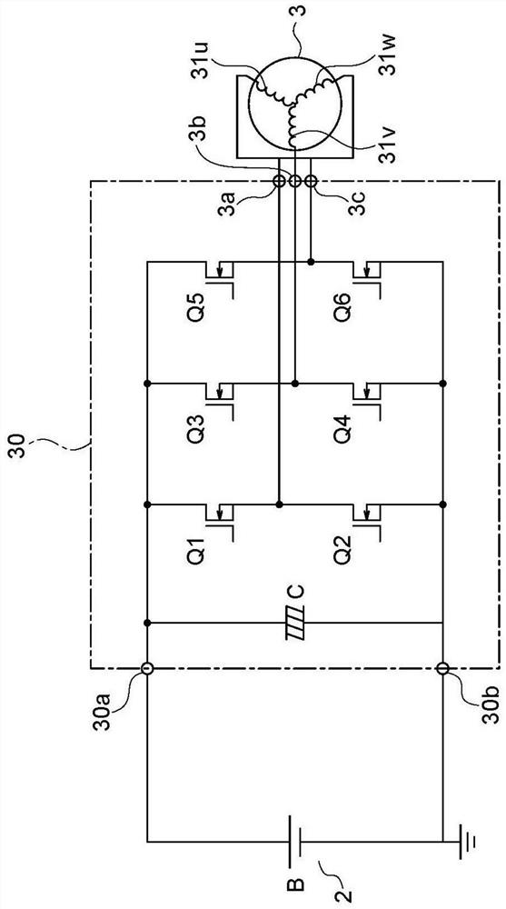
technical field [0001] The invention relates to a driving device, an electric vehicle and a control method of the driving device. Background technique [0002] In the past, electric two-wheeled vehicles using a battery as a power source and a three-phase motor (hereinafter referred to as a motor) as a power source have been widely known. [0003] In such an electric two-wheeled vehicle, in order to drive the motor, a three-phase full-bridge circuit (that is, an inverter circuit) equipped with a high-side switch and a low-side switch on each phase realizes the transmission from the battery to each phase of the motor. Coil energization control. [0004] During energization control, the switch is PWM-controlled according to the set duty ratio, and the torque corresponding to the duty ratio is output to the motor. In addition, as the energization method, 120° energization in which energization is performed in consecutive 120° energization cycles among the energization cycles a...

Claims


Application Information

Patent Timeline
Patent Type & Authority Applications(China)
IPC IPC(8): H02P27/08
CPCH02P27/08Y02T10/72
Inventor 目黑一由希井之口雄大石川淳木村吏
Owner SHINDENGEN ELECTRIC MFG CO LTD
Learn More