Linear motion curved surface sliding block mechanism for thumb rehabilitation training

A rehabilitation training and linear motion technology, applied in passive exercise equipment, physical therapy and other directions, can solve the problems of long treatment time, increase the difficulty of rehabilitation, lack of qualified therapists, etc., achieve easy use, promote patient recovery, reduce burden effect

Inactive Publication Date: 2020-11-10
CHANGZHOU INST OF MECHATRONIC TECH
View PDF4 Cites 0 Cited by
  • Summary
  • Abstract
  • Description
  • Claims
  • Application Information

AI Technical Summary

Problems solved by technology

Most patients undergo rehabilitation training under the guidance of rehabilitation physicians. Even if a small number of patients have mastered their own rehabilitation treatment methods, they still need to go to rehabilitation hospitals and re...

Method used


Image

  • Linear motion curved surface sliding block mechanism for thumb rehabilitation training
  • Linear motion curved surface sliding block mechanism for thumb rehabilitation training
  • Linear motion curved surface sliding block mechanism for thumb rehabilitation training

Examples


Embodiment 1

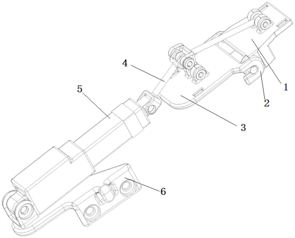
[0021] A linear motion curved surface slider mechanism for thumb rehabilitation training, comprising a front joint 1, a U-shaped joint 2, a rear joint 3, a link mechanism 4, a linear driver 5 and an L-shaped joint 6;

[0022] The front joint 1 is an inverted concave structure, and the two sides of the front joint 1 are provided with guard plates, and the back joint 3 and the two side guard plates of the front joint 1 are connected floatingly through U-shaped joints 2, and the thumb part composed of the front and rear joints passes through The link mechanism 4 is connected with the output end of the linear driver 5 ; the other end of the linear driver 5 is connected with the L-shaped coupling 6 . The tail end of the L-shaped connection 6 is provided with a connection hole, which can be connected with other mechanisms. The lower surface of the front joint 1 and the lower surface of the rear joint 3 are provided with linkage shafts. The angle of the U-shaped connection 2 is 180°...

Embodiment 2

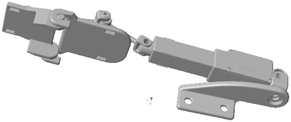
[0024] The composition of this thumb rehabilitation structure is as follows: figure 1 As shown, it is composed of front joint 1, rear joint 3, link mechanism 4, linear drive 5 and L-shaped connection. The U-shaped joint 2 on the rear joint is floatingly connected to the left and right side plates of the front joint through a U-shaped joint. The thumb part composed of the front and rear joints is connected to the linear actuator 5 through the link mechanism 4. The whole mechanism can be connected to other parts through the L-shaped joint 6. Institutional connections.

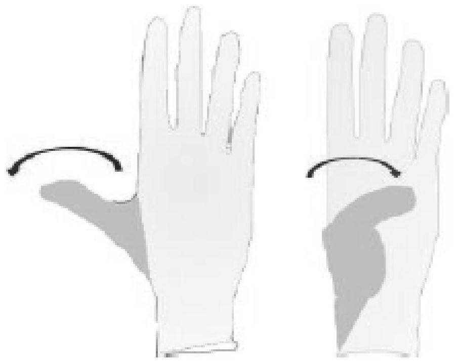
[0025] During use, the soft wristband is worn on the patient's thumb through the slots on both sides of the front and rear joints, the front joint 1 is located at the position of the patient's front phalanx, and the rear joint 3 is located above the rear phalanx. The linear motion of the linear actuator drives the curved surface of the thumb to move through the link mechanism to realize the flexion and extension...


PUM

PropertyMeasurementUnit
Angleaaaaaaaaaa

Abstract

The invention belongs to the technical field of rehabilitation devices, and relates to a linear motion curved surface sliding block mechanism for thumb rehabilitation training. The linear motion curved surface sliding block mechanism comprises a front joint, a U-shaped connector, a rear joint, a connecting rod mechanism, a linear driver and an L-shaped connector, wherein the front joint is of an inverted-U-shaped structure, protective plates are arranged on the two sides of the front joint, the rear joint is in floating connection with the protective plates on the two sides of the front jointthrough the U-shaped connector, a thumb part composed of the front joint and the rear joint is connected with the output end of the linear driver through the connecting rod mechanism, and the other end of the linear driver is connected with the L-shaped connector. According to the sliding block mechanism, the sliding block mechanism is established according to a typical adult thumb joint framework; therapeutic training can be provided for patients with different degrees of thumb injuries; the sliding block mechanism is suitable for clinic and also suitable home rehabilitation training, and burdens of patients and rehabilitation physicians are reduced; and on the basis of ergonomic design, the flexion and extension movement of thumbs can be realized.

Description

technical field [0001] The invention belongs to the technical field of rehabilitation devices, and relates to a rectilinear motion curved surface slider mechanism for thumb rehabilitation training. Background technique [0002] Stroke patients may have a variety of neurological deficit symptoms, which will lead to complete or partial loss of hand, wrist and forearm functions, and then cause significant defects in hand operation and daily work performance, seriously affecting the patient's ability and quality of life, giving The patient's family and society have brought great burden. It has been reported that more than 70% of stroke patients have upper limb dysfunction in the early stage of stroke, and more than 35% of stroke patients still have hand fine function decline 4 months after the onset. [0003] The current clinical treatment method is mainly based on the continuous passive movement theory, and repeatedly trains the affected limb of the patient. Most patients und...

Claims


Application Information

Patent Timeline
IPC IPC(8): A61H1/02
CPCA61H1/0288A61H2201/165A61H2205/067
Inventor 靳敏吴小邦苏郑佳彭仕林俞悦
Owner CHANGZHOU INST OF MECHATRONIC TECH
Why Eureka
Try Eureka