Thermal compensation type injection reaction system

A technology of reaction system and jet reactor, which is applied in the chemical industry, can solve the problems of application limitation, incapability of self-consumption of heat, lack of thermal compensation function, etc., to reduce the temperature rise of the system, improve the reaction effect, and avoid the temperature rise of the system Effect

Inactive Publication Date: 2020-11-10
SHANGHAI JIAO TONG UNIV
View PDF10 Cites 0 Cited by
  • Summary
  • Abstract
  • Description
  • Claims
  • Application Information

AI Technical Summary

Problems solved by technology

Patent CN201710359380.1 discloses a multi-stage, multi-functional jet reactor system and its operation method. The system can be used for multi-stage continuous reactions or multi-stage parallel reactions. It is used for exothermic reactions, especially strong exothermic reaction systems. The progress of the reaction can be controlled through a multi-stage reaction, and then the rate of heating can be controlled, but it sti

Method used


Image

  • Thermal compensation type injection reaction system
  • Thermal compensation type injection reaction system
  • Thermal compensation type injection reaction system

Examples


Embodiment 1

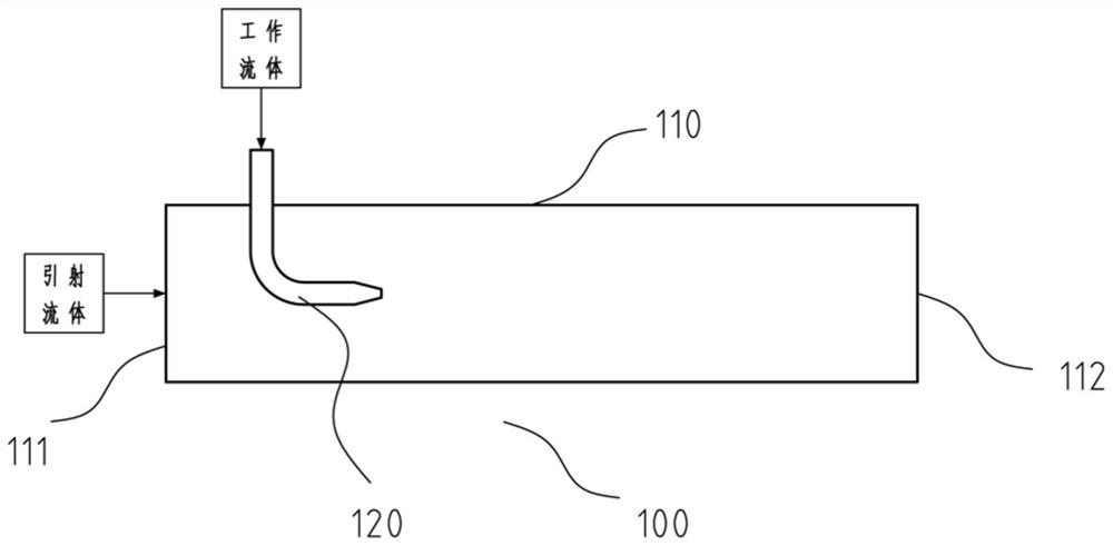
[0036] This embodiment provides a thermally compensated injection reaction system, such as figure 1 As shown, it includes a jet reactor 100, a working fluid, and an injection fluid. The jet reactor 100 includes a body 110 and a nozzle 120. The body 110 is provided with an injection fluid inlet 111 and a reactor outlet 112. The working fluid is sprayed into the body 110 through the nozzle 120, and the injection fluid enters the body 110 through the injection fluid inlet 111, and the working fluid and the injection fluid are mixed under the jet entrainment and generate heat Chemical reaction, in which at least one of the working fluid or the ejection fluid undergoes a gasification process, the latent heat of gasification required for the gasification process is compensated by the reaction heat of the exothermic chemical reaction, and the gasified and reacted material It is discharged from the reactor outlet 112.

[0037] In this embodiment, the nozzle 120 is a single nozzle typ...

Embodiment 2

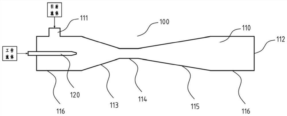
[0040] This embodiment provides a thermally compensated injection reaction system, such as figure 2 As shown, it includes a jet reactor 100, a working fluid, and an injection fluid. The jet reactor 100 includes a body 110 and a nozzle 120. The body 110 is provided with an injection fluid inlet 111 and a reactor outlet 112. The working fluid is sprayed into the body 110 through the nozzle 120, and the injection fluid enters the body 110 through the injection fluid inlet 111, and the working fluid and the injection fluid are mixed under the jet entrainment and generate heat Chemical reaction, in which at least one of the working fluid or the ejection fluid undergoes a gasification process, the latent heat of gasification required for the gasification process is compensated by the reaction heat of the exothermic chemical reaction, and the gasified and reacted material It is discharged from the reactor outlet 112.

[0041] In this embodiment, the nozzle 120 is a single nozzle ty...

Embodiment 3

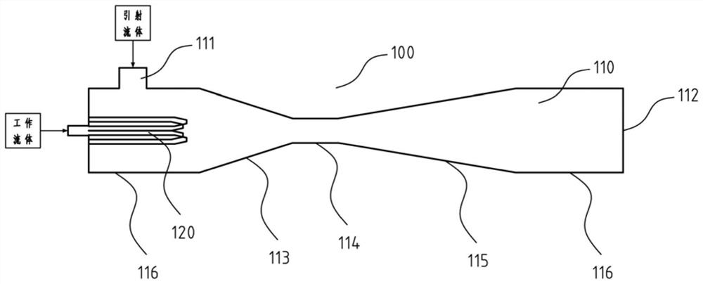
[0044] This embodiment provides a thermally compensated injection reaction system, such as image 3 As shown, it includes a jet reactor 100, a working fluid, and an injection fluid. The jet reactor 100 includes a body 110 and a nozzle 120. The body 110 is provided with an injection fluid inlet 111 and a reactor outlet 112. The working fluid is sprayed into the body 110 through the nozzle 120, and the injection fluid enters the body 110 through the injection fluid inlet 111, and the working fluid and the injection fluid are mixed under the jet entrainment and generate heat Chemical reaction, in which at least one of the working fluid or the ejection fluid undergoes a gasification process, the latent heat of gasification required for the gasification process is compensated by the reaction heat of the exothermic chemical reaction, and the gasified and reacted material It is discharged from the reactor outlet 112.

[0045] In this embodiment, the nozzle 120 is a multi-nozzle type...


PUM


Abstract

The invention relates to a thermal compensation type jet reaction system which comprises a jet reactor, a working fluid and a driving fluid; the jet reactor comprises a device body and a nozzle, the device body is provided with a driving fluid inlet and a reactor outlet, the working fluid is jetted into the device body through the nozzle, and the driving fluid enters the device body through the driving fluid inlet; then the working fluid and the driving fluid are mixed under the action of jet entrainment and undergo an exothermic chemical reaction, wherein at least one of the working fluid andthe driving fluid undergoes a gasification process and gasification latent heat required by the gasification process is compensated by reaction heat of the exothermic chemical reaction; finally, thegasified and reacted materials are discharged from an outlet of the reactor. Through energy matching of phase change heat and reaction heat, system temperature rise caused by reaction heat release isreduced or avoided, optimal reaction temperature distribution is obtained, reaction effects such as reaction efficiency improvement, side reaction reduction and product yield improvement are improved,in-situ utilization of the reaction heat can be realized, and energy waste is avoided.

Description

technical field [0001] The invention belongs to the technical field of chemical industry, and relates to a thermal compensation injection reaction system, in particular to a thermal compensation injection reaction system for exothermic reaction. Background technique [0002] Exothermic chemical reactions are very common in the chemical industry, such as oxidation, nitration, fluorination, phosgenation, and diazotization. Such reactions usually have a fast reaction rate and require harsh heat removal capabilities of the reactor. If the equipment such as the kettle is not properly controlled, it is easy to cause overheating, material leakage, intensified side reactions and even explosions. [0003] As we all know, the ejector is powered by the pressurized working fluid, and uses the entrainment of the ejection fluid by the jet and the "mixed shock wave" to transfer energy and mass. It has the advantages of simple structure, high reliability, and good sealing. Advantages, when...

Claims


Application Information

Patent Timeline
IPC IPC(8): B01J19/26
CPCB01J19/26
Inventor 李学刚肖文德阎建民罗漫
Owner SHANGHAI JIAO TONG UNIV
Why Eureka
Try Eureka