
Canning assembly line

An assembly line and canning technology, which is applied in the field of canning, can solve the problems of sufficient gas content, anti-foaming, and large amount of foam in the can, etc.

Inactive Publication Date: 2020-11-10
许伟忠
View PDF6 Cites 1 Cited by
  • Summary
  • Abstract
  • Description
  • Claims
  • Application Information

AI Technical Summary

Problems solved by technology

[0002] As a single production and processing line equipment for all kinds of aluminum can beverages, the canning line does not have obvious technical shortcomings in the canning processing of conventional ordinary beverages, but for the canning technology of carbonated beverages, due to the solubility of carbon dioxide High, the gas content of the beverage is relatively sufficient, it is easy to foam and produce anti-foaming phenomenon during the filling process, and the amount of foam in the tank will be too much at the moment of canning, which cannot meet the standard production requirements. Based on the above premise, this case A canning line was developed to solve this problem

Method used


Image

  • Canning assembly line
  • Canning assembly line
  • Canning assembly line

Examples


Embodiment

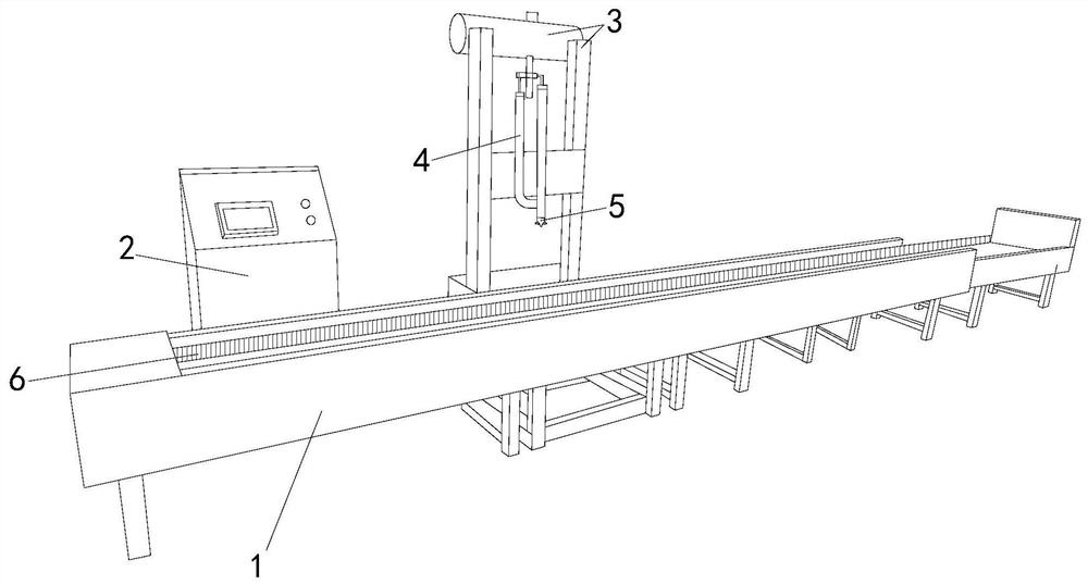
[0024] see figure 1 , the present invention provides a kind of canning assembly line, its structure comprises: Canning frame 1, numerical control table 2, liquid inlet tank 3, liquid injection pipe 4, defoaming pipe mechanism 5, rotary belt 6, described canning frame 1 is equipped with a numerical control platform 2 and a liquid inlet tank 3 respectively. The liquid inlet tank 3 is connected to the liquid injection pipe 4. The bottom end of the liquid injection pipe 4 is provided with a defoaming pipe mechanism 5. On the side, the canning frame 1 is the basic frame structure of the assembly line equipment, and it is also the conveying structure responsible for conveying empty cans to the carbonated beverage liquid raw material position for canning. Its structure presents a rectangular box structure with an unclosed top, with two sides The conveying member is composed of a rotary belt 6, the electronic cabinet structure with 2 digits of the numerical control table is used to c...

Embodiment 2

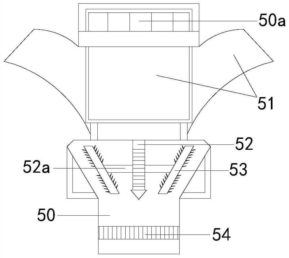
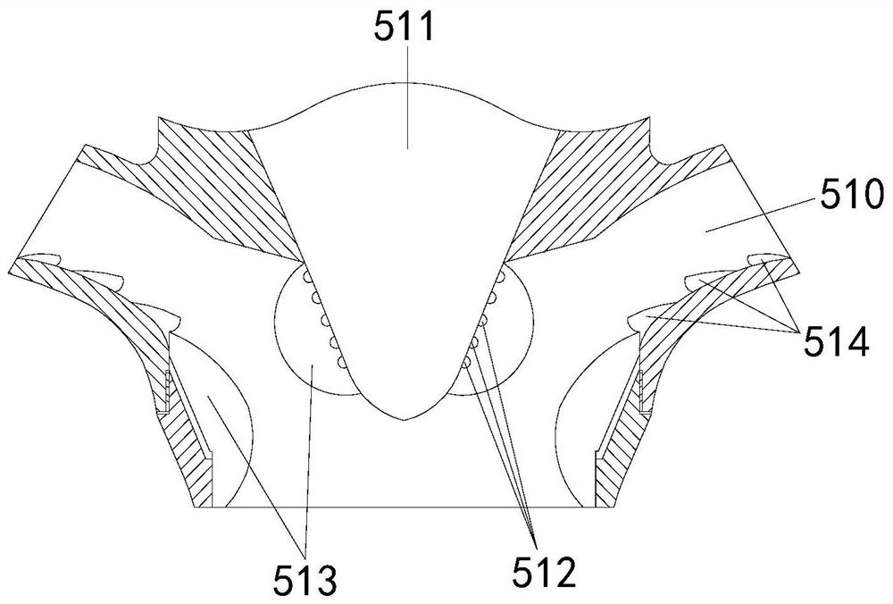
[0031] The description of the second embodiment drawn in conjunction with the first embodiment, combined with image 3 , Figure 4 and Figure 5 An air plunger 511 is provided between the elbow pipe walls 510, and the air plunger 511 communicates with the closed bag 513 through the provided air hole 512, and the side of the closed bag 513 is arranged with stop blocks 514, and the half Both sides of the shaft 530 are connected to the vibrating plate 531, and the side edge of the vibrating plate 531 is provided with penetrating teeth 532, and the penetrating ball 540 is connected to the bubble ball 542 through the rod joint 541, and the bottom end of the bubble ball 542 is provided with dense teeth When the cone 543 is filled, the liquid injection pipe 4 is first aligned with the empty beverage can. At this time, the liquid is conveyed downward, and the defoaming pipe mechanism 5 performs defoaming work synchronously. The vibrating plate 531 vibrates and simultaneously drives t...


PUM


Abstract

The invention discloses a canning assembly line which structurally comprises a canning rack, a numerical control table, a liquid inlet tank, a liquid injection pipe, a bubble removing pipe mechanism and wheel rotary belts; the side edge of the canning rack is provided with the numerical control table and the liquid inlet tank, the liquid inlet tank is connected with the liquid injection pipe, andthe tail end of the bottom of the liquid injection pipe is provided with the bubble removing pipe mechanism. The canning assembly line has the beneficial effects that a vibration cutting plate is adopted to generate the effects of high-speed puncturing and bubble breaking, in cooperation with a bubble removing net, bubbles are broken through sawteeth uniformly distributed on the surface of a dense-tooth cone, and the situation that the standard production requirement cannot be met due to the fact that a large number of bubbles are generated in the canning production process is avoided.

Description

technical field [0001] The invention relates to the field of canning, in particular to a canning assembly line. Background technique [0002] As a single production and processing line equipment for all kinds of aluminum can beverages, the canning line does not have obvious technical shortcomings in the canning processing of conventional ordinary beverages, but for the canning technology of carbonated beverages, due to the solubility of carbon dioxide High, the gas content of the beverage is relatively sufficient, it is easy to foam and produce anti-foaming phenomenon during the filling process, and the amount of foam in the tank will be too much at the moment of canning, which cannot meet the standard production requirements. Based on the above premise, this case A canning line was developed to solve this problem. Contents of the invention [0003] Aiming at the deficiencies of the prior art, the present invention is realized through the following technical solutions: a ...

Claims


Application Information

Patent Timeline
Patent Type & Authority Applications(China)
IPC IPC(8): B65B3/22B67D7/00B67D7/02B67D7/06B67D7/42A23L2/54
CPCA23L2/54B65B3/22B67D7/005B67D7/02B67D7/06B67D7/42
Inventor 许伟忠
Owner 许伟忠
Learn More