Oil-water separator for numerically-controlled machine tool

A technology of oil-water separator and numerically controlled machine tools, which is applied in the field of numerically controlled machine tools, and can solve problems such as blockage of the connection end face of the oil-water separator and the discharge port

Inactive Publication Date: 2020-11-10
广州佳优华信息科技有限公司
View PDF0 Cites 1 Cited by
  • Summary
  • Abstract
  • Description
  • Claims
  • Application Information

AI Technical Summary

Problems solved by technology

[0005] In order to solve the above technology, the oil-water separator is directly connected to the discharge port of the CNC machine tool, and some chips of the machined parts of the CNC machine tool will be thrown into the cooling tank with the centrifugal force during processing, and the coolant in the discharge port will be discharged into the oil-water Precipitation in the separator, with the continuous accumulation of debris, it is easy to block the connection end face of the oil-water separator and the discharge port

Method used


Image

  • Oil-water separator for numerically-controlled machine tool
  • Oil-water separator for numerically-controlled machine tool
  • Oil-water separator for numerically-controlled machine tool

Examples


Embodiment 1

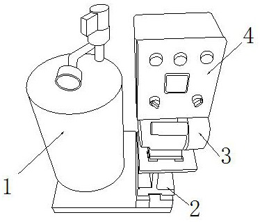
[0025] as attached figure 1 to attach Figure 5 Shown:

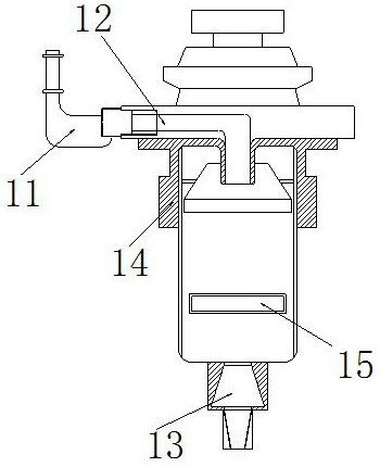
[0026] The invention provides an oil-water separator for a numerically controlled machine tool, the structure of which includes a separation mechanism 1, a fixed base 2, a motor 3, and a control center 4. The separation mechanism 1 is embedded and installed directly above the fixed base 2, and the fixed base 2 is provided with a motor 3, the motor 3 is located on the right side of the separation mechanism 1, and the control center 4 is installed and fixed directly above the motor 3 by welding; the separation mechanism 1 includes a connecting pipe 11, a flow pipe 12. Confluence port 13, filter element housing 14, separation port 15, the connecting pipe 11 is nested and installed on the left side of the flow pipe 12, the flow pipe 12 is inlaid directly above the filter element shell 14, the confluence port 13 is embedded and installed directly below the separation port 15, and the filter element housing 14 is fixed on th...

Embodiment 2

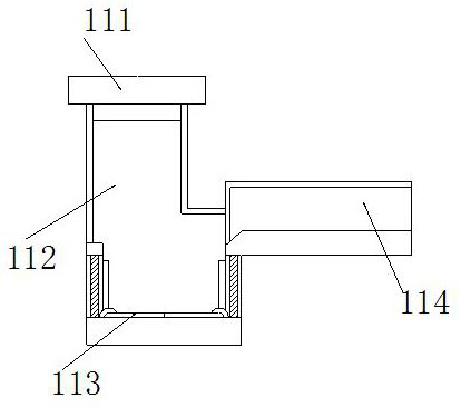
[0033] as attached Figure 6 To attach Figure 7 As shown: the separation pipe 114 includes a flow gap 141, a screening device 142, an embedded plate 143, and a flow pipe 144. The flow gap 141 is inlaid on the inner end surface of the separation pipe 114, and the screening device 142 is movably engaged and installed. Right above the embedded plate 143, the lower end of the embedded plate 143 is attached to the inner lower end surface of the separation pipe 114, the flow tube 144 is connected in series with the sedimentation tube 112, and the outer contour of the upper end of the embedded plate 143 is set It is in the shape of an obtuse triangle, so that the left end surface of the separation pipe 114 expands in a wide-angle manner, and can effectively accommodate the flowing coolant and debris during the flow.

[0034] Wherein, the screening device 142 includes a collection box 421, a handle 422, a filter screen 423, and an inlaid shell 424. The upper end surface of the collect...


PUM


Abstract

The invention discloses an oil-water separator for a numerically-controlled machine tool, which structurally comprises a separation mechanism, a fixing base, a motor and a control center, the separation mechanism is fixedly embedded right above the fixing base, the motor is arranged right above the fixing base, the motor is positioned on the right side of the separation mechanism, and the controlcenter is fixedly mounted right above the motor through welding. In the continuous precipitation process, a swing block is squeezed downwards, the swing block moves downwards with a rotating shaft asa center fulcrum and a sliding groove as a walking route, and in a moving process, the connecting end face of the lower end and a movable rod can be pushed towards the lower end of the outer side along with the outer contour of the lower end of the swing block and the inclined splayed design of a supporting mechanism; when the movable rod is pushed to be on the same horizontal line with the rotating shaft, the swing block swings downwards, a notch is opened to enable chippings located at the upper end of the notch to be dumped out, and chippings are prevented from being blocked in equipment.

Description

technical field [0001] The invention belongs to the field of numerical control machine tools, and more specifically relates to an oil-water separator for numerical control machine tools. Background technique [0002] The oil-water separator is a kind of equipment used with CNC machine tools. By connecting the connecting pipe to the discharge port of the machine tool, the coolant and oil discharged from the machine tool during the processing flow into the equipment, and the coolant and oil are separated by precipitation. Separation allows the coolant to flow back to the machine tool, saving resources. [0003] Based on the inventor's discovery above, there are mainly the following deficiencies in existing methods, such as: because the oil-water separator is directly connected to the discharge port of the CNC machine tool, and part of the debris of the machined parts of the CNC machine tool will be thrown away with the centrifugal force during processing. In the cooling tank,...

Claims


Application Information

Patent Timeline
Patent Type & Authority Applications(China)
IPC IPC(8): C02F9/02C02F1/40
CPCC02F1/001C02F1/40C02F1/52C02F2001/007
Inventor 江海霞
Owner 广州佳优华信息科技有限公司
Why Eureka
Try Eureka