Supercharge Your Innovation With Domain-Expert AI Agents!

Fabricated steel bar connecting assembly and assembling method

A connecting component and prefabricated technology, applied in the processing of building components, building reinforcements, building materials, etc., can solve the problems of high processing precision of threaded joints, time-consuming and labor-intensive, etc., to achieve quality and strength assurance, simple and fast operation, easy to use processing effect

Pending Publication Date: 2020-11-10
杨骥
View PDF0 Cites 1 Cited by
  • Summary
  • Abstract
  • Description
  • Claims
  • Application Information

AI Technical Summary

Problems solved by technology

[0006] The purpose of the present invention is to provide an assembled steel bar connection assembly, which solves the problems that the existing straight threaded connection of steel bars requires high processing precision for threaded joints and consumes time and effort during assembly.

Method used


Image

  • Fabricated steel bar connecting assembly and assembling method
  • Fabricated steel bar connecting assembly and assembling method
  • Fabricated steel bar connecting assembly and assembling method

Examples


Embodiment 1

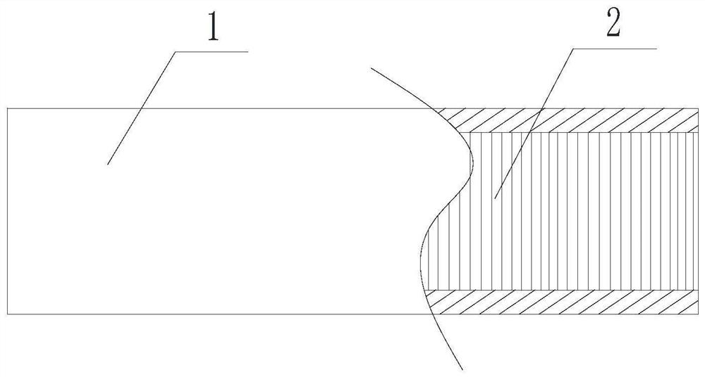
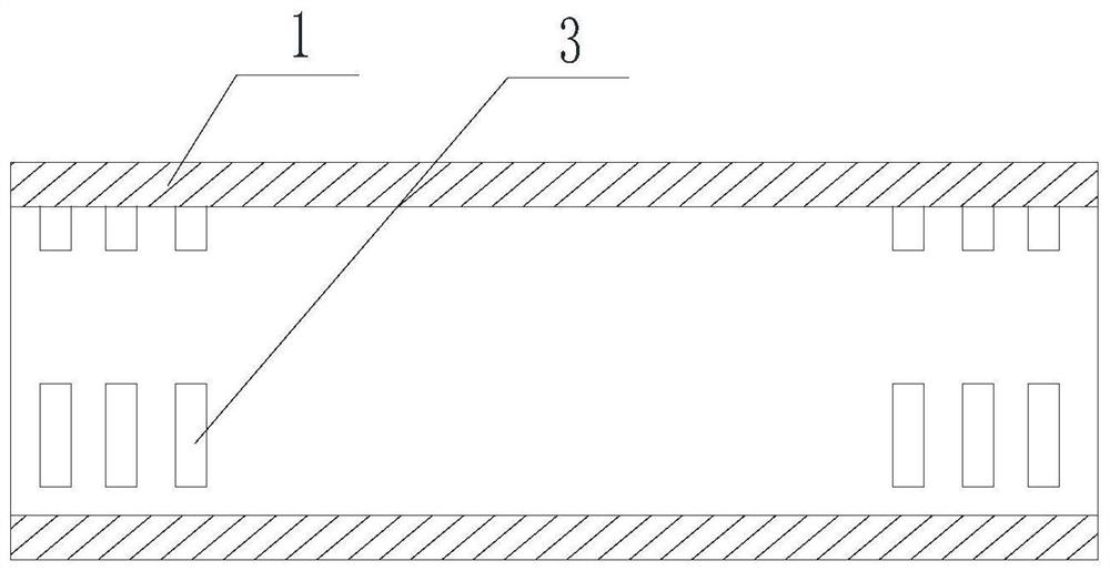
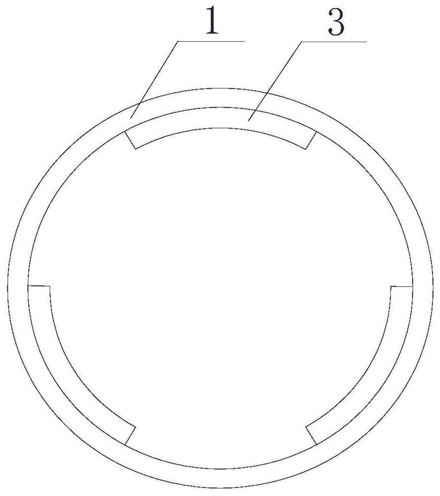
[0047] Such as Figure 2-Figure 9 As shown, the assembled steel bar connection assembly includes a sleeve 1 and a steel bar 5. Both ends of the inner wall of the sleeve 1 are provided with three first partition convex tooth structures in the axial direction. The first partition convex teeth The structure includes three first protruding teeth 3, and the three first protruding teeth 3 are arranged in an annular array on the inner wall of the sleeve 1, and the outer wall of one end of the steel bar 5 is provided with three second protruding teeth that cooperate with the first partition protruding tooth structure. The partition convex tooth structure, the second partition convex tooth structure includes 3 second convex teeth 6, and the 3 second convex teeth 6 are arranged in an annular array on the outer wall of one end of the steel bar 5, the first convex teeth 3 and The size and shape of the second protruding teeth 6 are the same, and the length of the second protruding teeth 6 ...

Embodiment 2

[0054] This embodiment is based on embodiment 1, and the difference of embodiment is:

[0055] Both ends of the inner wall of the sleeve 1 are provided with two first partition convex tooth structures, the first partition convex tooth structure includes four first convex teeth 3, and the end (joint) of the steel bar 5 is provided with Two second partition convex tooth structures, the second partition convex tooth structure includes four second convex teeth 6 .

Embodiment 3

[0057] This embodiment is based on embodiment 1, and the difference of embodiment is:

[0058] Both ends of the inner wall of the sleeve 1 are provided with four first partition convex tooth structures, the first partition convex tooth structure includes two first convex teeth 3, and the end (joint) of the steel bar 5 is provided with There are 4 second partition convex tooth structures, and the second partition convex tooth structure includes 2 second convex teeth 6 .


PUM


Abstract

The invention discloses a fabricated steel bar connecting assembly and an assembling method. The steel bar connecting assembly comprises a sleeve and a steel bar, the two ends of the inner wall of thesleeve are each provided with a plurality of first partition convex tooth structures in the axial direction, each first partition convex tooth structure at least comprises two first convex teeth, a second partition convex tooth structure matched with the first partition convex tooth structures is arranged on the outer wall of one end of the steel bar, the second partition convex tooth structure at least comprises two second convex teeth, and the length of each second convex tooth in the circumferential direction is smaller than or equal to the gap between every two adjacent first convex teethin the circumferential direction; and the length of each second convex tooth in the axial direction is smaller than or equal to the gap between every two adjacent first convex teeth in the axial direction, and wedge blocks are further included and are in interference fit with the sleeve, the steel bar and the gap formed between every two adjacent first convex teeth. The problems that due to existing steel bar straight thread connection, the requirement for threaded connector machining precision is high, and time and labor are wasted during assembling are solved.

Description

technical field [0001] The invention relates to the technical field of building construction, in particular to an assembled steel bar connection assembly and an assembly method. Background technique [0002] In the process of building construction, the connection of steel bars is inevitable, and the connection methods of steel bars generally include: binding lap joints, welding connections and mechanical connections. The mechanical connection methods of steel bars include straight thread and tapered thread. Among them, the most widely used is the straight thread connection of steel bars, and the straight thread connection is realized by using steel bar joints, such as figure 1 As shown, the steel bar joint includes a sleeve 1, the inner wall of the connecting tube 1 is provided with a precision thread 2, and a precision thread matched with the thread 2 is processed at one end of the steel bar. [0003] The straight thread connection of steel bar has the following disadvanta...

Claims


Application Information

Patent Timeline
Patent Type & Authority Applications(China)
IPC IPC(8): E04C5/16E04G21/12
CPCE04C5/165E04G21/122
Inventor 杨骥杨明洋
Owner 杨骥
Features
  • R&D
  • Intellectual Property
  • Life Sciences
  • Materials
  • Tech Scout
  • Unparalleled Data Quality
  • Higher Quality Content
  • 60% Fewer Hallucinations
Learn More