Air conditioner air supply device

A technology of air supply device and air outlet device, which is applied in air conditioning system, space heating and ventilation, space heating and ventilation details, etc. It can solve the problems of affecting comfort, single air outlet direction, poor blowing experience, etc. Achieve the effect of improving the comfort of use, increasing the air outlet area, and avoiding the concentration of wind direction

Active Publication Date: 2020-11-10
XI AN JIAOTONG UNIV
View PDF7 Cites 4 Cited by
  • Summary
  • Abstract
  • Description
  • Claims
  • Application Information

AI Technical Summary

Problems solved by technology

The air duct structure is complex, the air supply mode is single, and the airflow blown out is mostly mechanical wind, giving people a poor blowing experience
The air outlet device of the air outlet is mostly fixed, and the deflection angle of the air outlet has certain limitations. The air outlet can only be adjusted in the horizontal or vertical direction, and there will be a dead angle of air supply, which cannot realize large wide-angle and wide-range. air supply
At the same time, due to the small change in the angle of the air outlet, the air flow in the room is uneven, and the direction of the air outlet is a single vertical and horizontal direction, which is likely to cause concentrated air supply and local overcooling, and most of the air blown out is mechanical wind, which affects people. comfort

Method used


Image

  • Air conditioner air supply device
  • Air conditioner air supply device
  • Air conditioner air supply device

Examples


Embodiment Construction

[0039] The present invention is described in further detail below in conjunction with accompanying drawing:

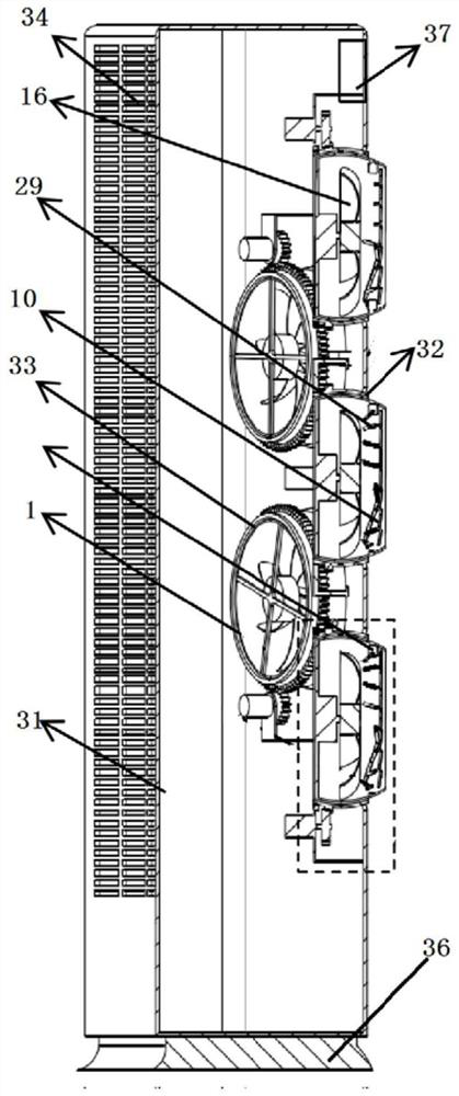
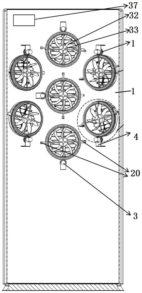
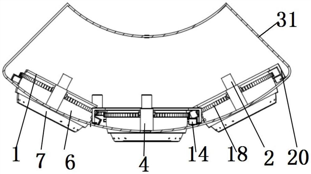
[0040] Such as Figure 1 to Figure 7As shown, an air-conditioning air supply device includes an air-conditioning box body 31, and a plurality of air outlets 32 are provided on the front panel of the air-conditioning box body 31, and an air outlet device 33 is installed at the air outlet place through a bearing bracket 1, and the bearing bracket 1 is fixed On the front panel of the air conditioning box 31; the air outlet device 33 includes the air duct surface frame 6 and the rotating air duct 7, the air duct surface frame 6 and the rotating air duct 7 are axial through-hole structures, and the rotating air duct 7 is nested In the inner cavity of the air duct surface frame 6, both sides of the rotating air duct 7 are rotationally connected with the air duct surface frame 6 through the rotating air duct rotating shaft 21, and the axis of the rotating air duct rotating sh...


PUM


Abstract

The invention discloses an air conditioner air supply device. Multiple air outlets are formed in a front panel of an air conditioner box, air outlet devices are installed in the air outlets through bearing supports, air duct surface frames and rotating air ducts which are all of through hole structures in the axial directions are adopted for forming the air outlet devices, the rotating air ducts are embedded into inner cavities of the air duct surface frames, and are sleeved with the inner cavities of the air duct surface frames, two sides of each rotating air duct are rotatably connected withthe corresponding air duct surface frame through corresponding rotating air duct rotating shafts, and the axes of the rotating air duct rotating shafts are perpendicular to those of the air duct surface frames; the outer surfaces of the rotating air ducts and inner cavity surfaces of the air duct surface frames are all spherical surfaces, a corresponding swing blade set is arranged on the end surface of one side of each rotating air duct, the air duct surface frames and the rotating air ducts are used for forming the air outlet devices, in shapes of universal balls, which can rotate relatively, the angles and the directions of air supply openings of the rotating air ducts can be adjusted to make air flows reach assigned places under cooperation of the swing blade sets, thus personalized precise air supply is achieved, the air flows are made to reach required places, thus multidimensional dynamic air supply is achieved, the turbulivity of the indoor air flows is improved, and outlet air of the air outlet devices is made to be more similar to simulated natural air.

Description

technical field [0001] The invention belongs to the field of air-conditioning devices, and in particular relates to an air-conditioning air supply device. Background technique [0002] Green, low-carbon and sustainable development has become a global consensus. As one of the products of white goods, the cabinet air conditioner will inevitably be based on the basic principles of low-carbon, green and sustainable development in the future. At the same time, based on the user's requirements for personalized air supply and dynamic air supply, the traditional basic cooling and heating modes of air conditioners can no longer meet the requirements. The core air supply mode of the traditional cabinet air conditioner is mostly a centrifugal impeller or a single outlet air supply mode of the mixed flow impeller. The air duct structure is complex, the air supply mode is single, and the airflow blown out is mostly mechanical wind, which gives people a poor blowing experience. The air...

Claims


Application Information

Patent Timeline
Patent Type & Authority Applications(China)
IPC IPC(8): F24F1/0014F24F11/79F24F13/14F24F13/20
CPCF24F1/0014F24F11/79F24F13/1413F24F13/20
Inventor 刘小民王加浩田晨晔席光
Owner XI AN JIAOTONG UNIV
Why Eureka
Try Eureka