
Strong coupling device for coupling ring of microwave resonant cavity

A microwave resonant cavity and coupling ring technology, applied in resonators, waveguide devices, electrical components, etc., can solve problems such as easy energy leakage, achieve the effect of enhancing the adjustment ability and eliminating the influence of microwave energy radiation leakage

Pending Publication Date: 2020-11-10
UNIV OF ELECTRONICS SCI & TECH OF CHINA
View PDF0 Cites 1 Cited by
  • Summary
  • Abstract
  • Description
  • Claims
  • Application Information

AI Technical Summary

Problems solved by technology

[0005] The purpose of the present invention is to provide a microwave resonant cavity coupling ring strong coupling device, which solves the problem that the traditional coupling ring excitation microwave resonant cavity device easily leaks energy when the coupling hole is large, and can set a large-sized coupling hole without Due to energy leakage due to oversize, it is also possible to adjust the size of the coupling loop and fine-tune to improve the reflection performance of the coupling loop port

Method used


Image

  • Strong coupling device for coupling ring of microwave resonant cavity
  • Strong coupling device for coupling ring of microwave resonant cavity
  • Strong coupling device for coupling ring of microwave resonant cavity

Examples


Embodiment 1

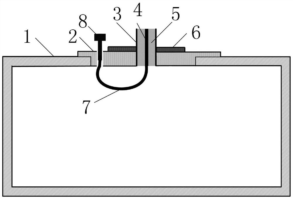
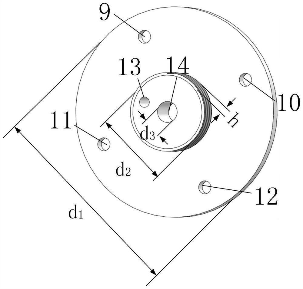
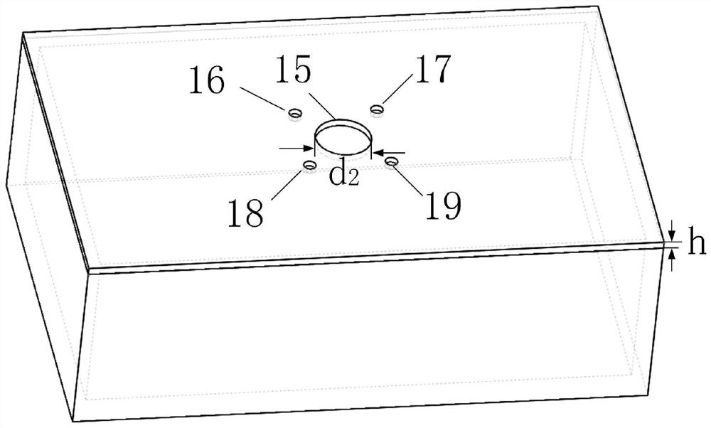
[0023] A microwave resonator coupling ring strong coupling device, as shown in Figure 1, comprising: a microwave resonator 1, a T-shaped columnar metal cap structure 2, a coaxial coupling ring structure, a coaxial flange 6 and fine-tuning screws 8 . Among them, the T-shaped columnar metal cap structure 2 and the coaxial flange 6 are located at the strongest magnetic field of the microwave resonator 1, and the T-shaped columnar metal cap structure 2 is fixed on the outer wall of the microwave resonator 1, and the coaxial line The flange plate 6 is fixed on the T-shaped columnar metal cap structure 2, and the fine-tuning screw 8 is threadedly connected to the T-shaped columnar metal cap structure 2, and its position is connected with the inside of the microwave resonator 1, and the T-shaped columnar metal cap structure 2 And the material of fine-tuning screw 8 is metal. The coaxial coupling ring structure is composed of a coaxial cable and an inner conductor ring structure 7. T...


PUM


Abstract

The invention discloses a strong coupling device for a coupling ring of a microwave resonant cavity. The device comprises the microwave resonant cavity, a T-shaped columnar metal cap structure, a coaxial line coupling ring structure, a coaxial line flange plate and a fine adjustment screw, wherein the T-shaped columnar metal cap structure and the coaxial flange plate are positioned at the strongest magnetic field of the microwave resonant cavity; the fine adjustment screw is in threaded connection with the T-shaped columnar metal cap structure, and the position of the fine adjustment screw iscommunicated with the microwave resonant cavity; the coaxial line coupling ring structure is composed of a coaxial cable and an inner conductor ring structure, and the coaxial cable is inserted into the coaxial line flange plate and the T-shaped columnar metal cap structure; and the inner conductor ring structure is a ring structure which is formed by bending a coaxial inner conductor connected with the coaxial cable and connecting the coaxial inner conductor with the tail end of the fine tuning screw. According to the device, energy leakage caused by overlarge size of the coupling hole in thewall of the resonant cavity is avoided, and the size of the coupling ring can be adjusted to improve the reflection performance of the port of the coupling ring.

Description

technical field [0001] The invention relates to a microwave resonant cavity, in particular to a microwave resonant cavity coupling ring strong coupling device. Background technique [0002] Microwave resonators are widely used in microwave signal sources, microwave filters and wavelength meters, and are a basic microwave component. The excitation and coupling of microwave resonators usually use two classical sensors: electrical probes and coupling rings, both of which can be fabricated using coaxial cables. Among them, the electric probe is a structure formed by stripping off a part of the outer conductor and the medium of the coaxial cable to expose a certain length of the inner conductor. The electric probe can usually be excited in the area where the main mode electric field of the microwave resonator is strong. The needle is parallel to the electric field direction of the main mode, and the main mode can be excited. The coupling ring is a structure formed by bending th...

Claims


Application Information

Patent Timeline
Patent Type & Authority Applications(China)
IPC IPC(8): H01P1/00H01P1/04H01P7/06
CPCH01P7/06H01P1/04H01P1/00H01P1/045
Inventor 高勇陈天润高冲张云鹏李灿平李恩
Owner UNIV OF ELECTRONICS SCI & TECH OF CHINA
Learn More