Full-automatic glue brushing line for shoemaking

A fully automatic, glue brushing technology, applied in the direction of pretreatment surface, coating, surface coating liquid device, etc., can solve the problems of easy glue blocking, insufficient glue adhesion, uneven glue quantity, etc.

Active Publication Date: 2020-11-13
XR AUTOMATION EQUIPGZ CO LTD
View PDF11 Cites 3 Cited by
  • Summary
  • Abstract
  • Description
  • Claims
  • Application Information

AI Technical Summary

Problems solved by technology

[0006] The purpose of the invention is to provide a fully automatic gluing line for shoemaking. By setting a positioning mechanism, a robot component, a gluing system shoe and an oven on the frame, the automatic positioning, automatic grabbing and automatic gluing of the shoe last are completed, forming an automatic The assembly line produc

Method used


Image

  • Full-automatic glue brushing line for shoemaking
  • Full-automatic glue brushing line for shoemaking
  • Full-automatic glue brushing line for shoemaking

Examples


Embodiment 1

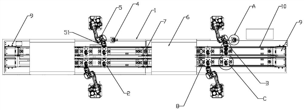
[0089] A fully automatic glue brushing line for shoemaking, such as Figure 1-5 As shown, it includes: a frame 1, a shoe last positioning plate 2, a positioning mechanism 3, a robot assembly 5, a glue brushing system 4, and a control system; the control system is used to control the transmission device 10, the positioning mechanism 3, and the robot Component 5 and gluing system 4. The frame 1 is provided with a conveying device 10 for conveying the shoe last positioning board 2. The conveying device 10 includes transmission chains or belts respectively arranged on both sides of the machine tool. The length direction of the shoe last positioning plate 2 is set across the transmission chains or belts on both sides for transmission. The shoe last positioning plate 2 is used for positioning the shoe last 23; the positioning mechanism 3 is arranged on the frame 1, the positioning mechanism 3 is used for positioning the shoe last positioning plate 2, and the conveying device 10 wil...

Embodiment 2

[0120] This embodiment only describes the differences from the above-mentioned embodiments, and the similarities between this embodiment and the above-mentioned embodiments will not be repeated. In this embodiment, the limiting plate 24 is a straight plate, and one end of the straight plate extends upwards. out of the upper surface of the shoe last positioning plate 2, the other end of the straight plate extends downward and is placed outside the transmission chain or belt in the conveying device 10, and the limiting plate 24 is positioned with the shoe last The connection position of the plate 2 is close to the upper end of the limiting plate 24, the positioning sensor 22 is arranged on the upper end of the limiting plate 24, or the positioning sensor 22 is arranged on the upper end of the limiting plate 24 and Between the joint of the limiting plate 24 and the shoe last positioning plate 2 .

Embodiment 3

[0122] This embodiment only describes the differences from the above-mentioned embodiments, and the similarities between this embodiment and the above-mentioned embodiments will not be repeated. In this embodiment, the bottom of the stop roller 8 is connected to a cylinder device. When the shoe last positioning plate 2 After completely passing the stop roller 8 on one side of the positioning mechanism 3, that is, after detecting that both sides of the shoe last positioning plate 2 have passed the stop roller 8, the stop roller 8 rises, thereby limiting the subsequent shoe last positioning plate 2 to continue to Front conveying ensures that there is only one shoe last positioning plate 2 above each positioning mechanism 3. When the shoe last positioning plate 2 leaves the positioning mechanism 3, the stop roller 8 descends, and the shoe last positioning plate 2 passes through the stop on the other side of the positioning structure. The rollers 8 continue to be transported forwar...


PUM


Abstract

The invention discloses a full-automatic glue brushing line for shoemaking. The full-automatic glue brushing line for shoemaking comprises a rack, a shoe tree positioning plate, a positioning mechanism, a robot assembly and a glue brushing system; the rack is provided with a conveying device used for conveying the shoe tree positioning plate; the shoe tree positioning plate is used for positioninga shoe tree; the positioning mechanism is used for positioning the shoe tree positioning plate, and the conveying device conveys the shoe tree positioning plate to the upper part of the positioning mechanism; the robot assembly comprises a robot body and a gripper mechanism, the gripper mechanism is fixed at the end part of the robot body, and the gripper mechanism is used for gripping the shoe tree on the shoe tree positioning plate; and the glue brushing system is used for gluing the shoe tree. According to the full-automatic glue brushing line for shoemaking, the positioning mechanism, therobot assembly, the glue brushing system and an oven are arranged on the rack, automatic shoe tree positioning, automatic gripping and automatic glue brushing are completed, an assembly line production mode combining automatic glue brushing and baking is formed, the traditional method of manual glue brushing is replaced, and automatic production is realized.

Description

technical field [0001] The invention relates to the field of shoemaking, in particular to a fully automatic glue brushing line for shoemaking. Background technique [0002] In the shoe-making industry, the traditional handicraft production is to manually apply glue to insoles, uppers, and soles, and then bake them. Not only is the efficiency low, but the labor cost is also increasing year by year, and it is difficult to guarantee the quality. Moreover, the existing shoe-making equipment is almost all manual glue brushing, which is inefficient, harmful to the health of operators, and high in personnel costs. Existing automatic brushing equipment mostly uses automatic glue spraying technology, which sprays glue onto the surface of the shoe last through the glue spraying system, but the glue spraying technology is prone to many problems such as nozzle blockage, and often causes waste of glue resources, which seriously affects the manufacturing process. Development of shoe prod...

Claims


Application Information

Patent Timeline
IPC IPC(8): B05C9/14B05C13/02B05C1/02B05C11/10B05D3/02
CPCB05C1/02B05C9/14B05C11/1002B05C13/02B05D3/0272
Inventor 刘业涛陈龙刘业根
Owner XR AUTOMATION EQUIPGZ CO LTD
Why Eureka
Try Eureka