Injection molding machine detection device capable of performing real-time detection

A detection device and real-time detection technology, applied in the field of injection molding, can solve problems such as cracking of injection molded products, inconvenient use, complex structure, etc., and achieve the effect of safe and reliable use, convenient use, and simple structure

Inactive Publication Date: 2020-11-13
刘雄
View PDF0 Cites 2 Cited by
  • Summary
  • Abstract
  • Description
  • Claims
  • Application Information

AI Technical Summary

Problems solved by technology

[0003] In order to ensure the quality of injection molding, it is necessary to pay attention to controlling the injection pressure and injection speed during the use of the injection molding machine. Excessive injection pressure and too fast injection speed will cause the injection molded products to crack due to excessive internal stress. The injection molding machine currently in production Most of them are detected by installing sensors and other equipment, but the sensors need to install additional electric drives and other devices, the structure is complex, the cost is high, and it is inconvenient to use

Method used


Image

  • Injection molding machine detection device capable of performing real-time detection
  • Injection molding machine detection device capable of performing real-time detection
  • Injection molding machine detection device capable of performing real-time detection

Examples


Embodiment Construction

[0022] The following will clearly and completely describe the technical solutions in the embodiments of the present invention with reference to the accompanying drawings in the embodiments of the present invention. Obviously, the described embodiments are only some, not all, embodiments of the present invention. Based on the embodiments of the present invention, all other embodiments obtained by persons of ordinary skill in the art without making creative efforts belong to the protection scope of the present invention.

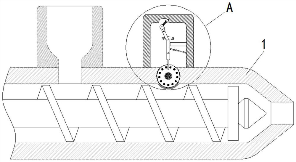
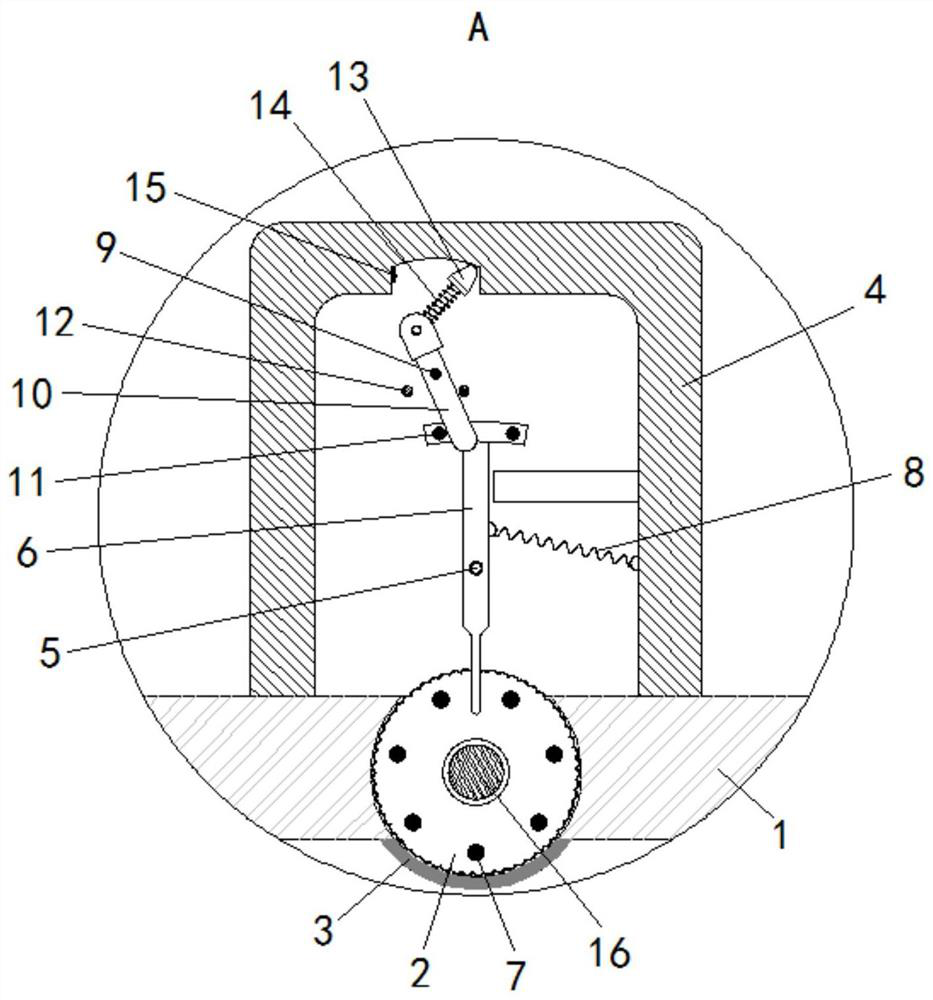
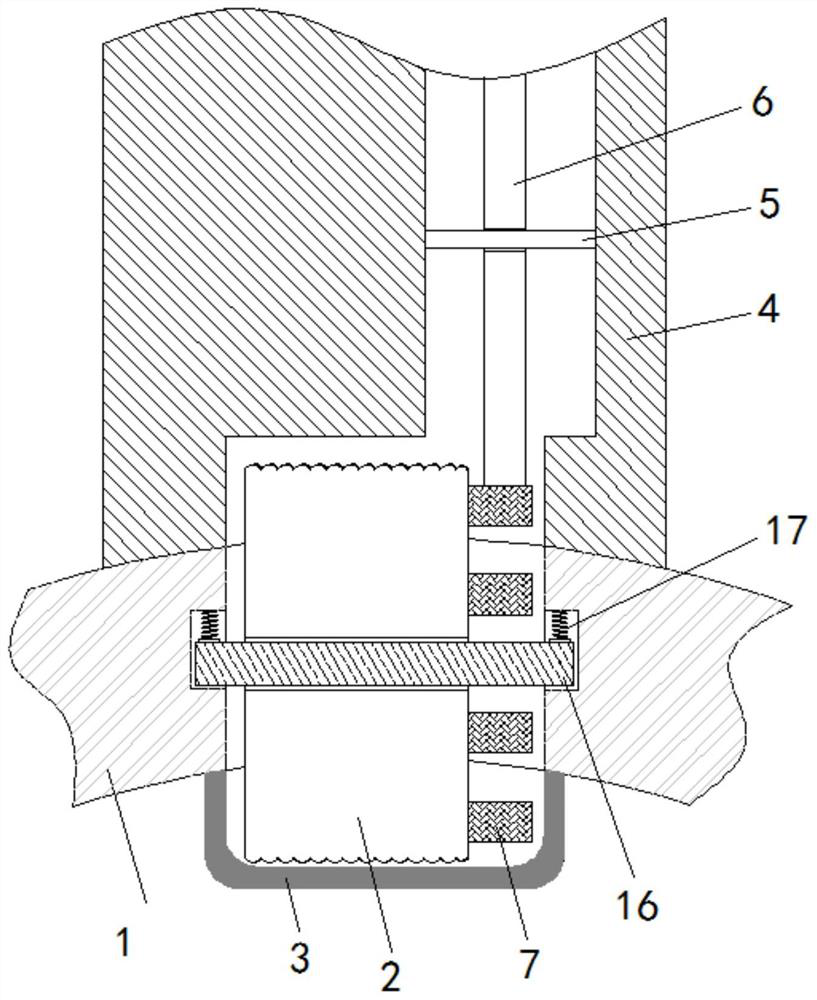
[0023] see Figure 1-3 , an injection molding machine detection device for real-time detection, including a main body 1, a main shaft 16 is slidably connected to the top wall of the main body 1, a positioning spring 17 is installed on the top of the main shaft 16, and a turntable 2 is movably sleeved on the outer side of the main shaft 16, A sealing gasket 3 is provided on the inner top wall of the main body 1 and outside the turntable 2 to protect the turntab...


PUM


Abstract

The invention relates to the technical field of injection molding and discloses an injection molding machine detection device capable of performing real-time detection. The injection molding machine detection device capable of performing real-time detection comprises a main machine body; a main shaft is connected to the interior of the top wall of the main machine body in a sliding manner; a rotating disc is connected to the external side of the main shaft in a movable sleeving manner; a detection rod is connected to the external side of a lower fixing shaft and the front surface of the rotating disc in a movable sleeving manner; a tension spring is fixedly connected to the right side of the detection rod; and a rotating plate is connected to the external side of an upper fixing shaft andthe front surface of the detection rod in a movable sleeving manner. The rotating disc is driven to rotate while plastics flow in the main machine body, the rotating disc continuously shifts the detection rod to deflect in a reciprocating manner by using a circular rod, and the deflection amplitude of the detection rod is related to the speed of the rotating disc; when the injection molding speedis too high, the deflection amplitude of the detection rod is increased; the rotating plate and an ejection plate are driven to deflect to the left side by using a shifting block, the ejection plate touches a switch key, and a warning device starts to send a warning signal to remind working personnel of performing detection and adjustment so as to realize an automatic reminding function is realized while the injection molding speed is too high; and therefore, the structure is simple, and the use is convenient.

Description

technical field [0001] The invention relates to the technical field of injection molding, in particular to an injection molding machine detection device for real-time detection. Background technique [0002] In the process of processing plastic products, injection molding is generally realized by injection molding machines. The advantages of using injection molding methods are fast production speed, high efficiency, and automatic operation can be realized. Moreover, the processing shape is changeable and the product size is precise. Therefore, injection molding is widely used in the fields of mass production and complex shape products. [0003] In order to ensure the quality of injection molding, it is necessary to pay attention to controlling the injection pressure and injection speed during the use of the injection molding machine. Excessive injection pressure and too fast injection speed will cause the injection molded products to crack due to excessive internal stress. T...

Claims


Application Information

Patent Timeline
IPC IPC(8): B29C45/77B29C45/84
CPCB29C45/77B29C45/84
Inventor 刘雄
Owner 刘雄
Why Eureka
Try Eureka