
Stability-fused intelligent automobile path tracking control method

A technology of path tracking and control methods, applied in the direction of control devices, etc., can solve the problems of reduced vehicle tracking accuracy, inability to meet stability, poor matching of predicted time domain values ​​and road curvature, etc.

Pending Publication Date: 2020-11-13
HARBIN UNIV OF SCI & TECH
View PDF0 Cites 16 Cited by
  • Summary
  • Abstract
  • Description
  • Claims
  • Application Information

AI Technical Summary

Problems solved by technology

This method only considers the vehicle stability constraints, it is difficult to guarantee the driving of the vehicle on complex road surfaces, and only considers the road information under the current coordinates. The vehicle preview distance does not change with the road curvature and vehicle speed, and cannot fully reflect the complex driving conditions of actual driving.
The curvature of the road is the curvature of the current driving position of the vehicle, and the curvature of the preview point is not considered. Only relying on the model prediction algorithm for calculation and prediction will cause the vehicle to have poor predictability of the road ahead
[0003] Moreover, most of the controllers designed based on model predictive control usually predict a constant value in the time domain, which will lead to poor matching between the predicted time domain value and the road curvature when the vehicle is on a large curvature curve, resulting in a decrease in vehicle tracking accuracy. ; Although this type of controller can ensure that the vehicle tracks the reference path more accurately under medium and low speed conditions, it is only constrained by the front wheel angle and cannot satisfy the stability of the vehicle at high speeds.

Method used

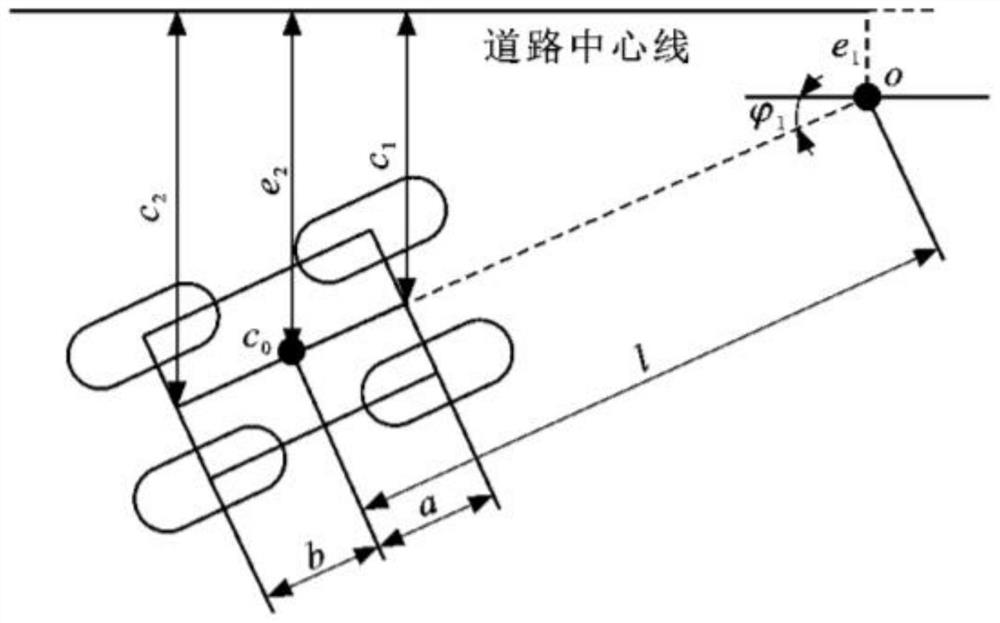

Image

  • Stability-fused intelligent automobile path tracking control method
  • Stability-fused intelligent automobile path tracking control method
  • Stability-fused intelligent automobile path tracking control method

Examples


Embodiment Construction

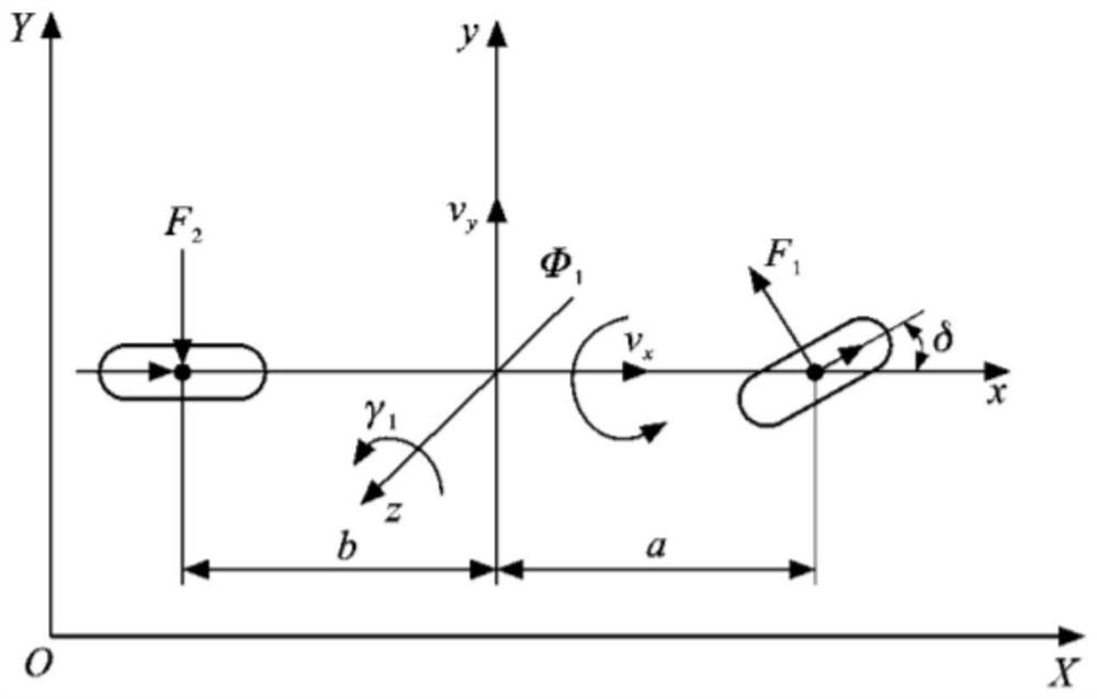
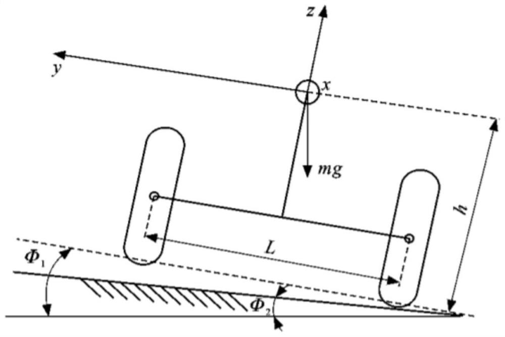
[0095] The present invention provides an intelligent vehicle path tracking control method with fusion stability, comprising the following steps: S1, establishing an equivalent dynamic model of a high-speed vehicle considering road terrain

[0096] S1.1, the high-speed vehicle dynamics model is the basis for studying the path-following control of high-speed unmanned vehicles considering terrain conditions, but an overly complex model will increase the calculation time and reduce real-time performance. On the premise of ensuring the control effect, the following simplifications are made to improve the calculation efficiency: Simplify to a single-track model; directly use the front wheel rotation angle as the system control quantity.

[0097] Based on the above settings, the figure 1 and figure 2 In the equivalent dynamic model of the high-speed vehicle shown, XOY is the earth coordinate system, X, Y are the longitudinal and transverse directions of the vehicle in the earth co...


PUM


Abstract

The invention provides a stability-fused intelligent automobile path tracking control method, and aims to improve the path tracking precision and improve the automobile stability. The method comprisesthe steps of establishing a high-speed vehicle equivalent dynamic model and a vehicle preview error model considering pavement topography, designing a preview distance generator, and establishing a function relationship between a prediction time domain and road curvature. A path tracking controller is designed based on a model prediction control algorithm; an index model is used for representingthe expected speed of the vehicle, and a proportional-integral-differential longitudinal controller is designed; meanwhile, a mass center slip angle phase plane graph is used for representing vehiclestability characteristics, and a proportional-integral-differential vehicle stability controller is designed. According to the control method provided by the invention, the vehicle tracking performance can be optimized on pavements with different adhesion coefficients, and the problem of low tracking precision on a large-curvature road is solved. The path tracking precision under the high-speed working condition is improved, and the driving stability is improved.

Description

technical field [0001] The invention relates to a track tracking control method of an intelligent vehicle, in particular to a track tracking control method of an intelligent vehicle integrating stability. Background technique [0002] Path tracking is one of the key technologies to realize the automatic driving of smart cars. It refers to the realization of the car's accurate, fast and stable driving along the desired path through autonomous steering. The complex driving conditions of smart cars have strong coupling characteristics. In the past, the control algorithm for a single working condition could not meet the complex working conditions of the car. Model prediction algorithm has been widely used in the field of vehicle path tracking control because it can effectively solve problems with constraints. In addition, by establishing a preview model, the curvature of the road ahead can be introduced, and the curvature of the preview point within a distance in front of the d...

Claims


Application Information

Patent Timeline
IPC IPC(8): B60W30/165B60W50/00
CPCB60W30/165B60W50/00B60W2050/0031B60W2050/0011
Inventor 翟元盛赵文凯
Owner HARBIN UNIV OF SCI & TECH
Learn More