Combined yarn carrier guiding device of knitting machine

A guiding device and combined technology, applied in the direction of woven fabrics, textiles and papermaking, can solve the problems of low manufacturing yield, long processing cycle, difficult to replace, etc., and achieve the effect of high yield, short processing cycle and easy replacement.

Pending Publication Date: 2020-11-13
XUZHOU HENGHUI BRAIDING MACHINE
View PDF0 Cites 2 Cited by
  • Summary
  • Abstract
  • Description
  • Claims
  • Application Information

AI Technical Summary

Problems solved by technology

[0004] The purpose of the present invention is to provide a combined yarn carrier guide device for a knitting machine, which solves the problems of low manufacturing yield, long processing cycle, high cost and difficult replacement of the existing yarn carrier guide device

Method used


Image

  • Combined yarn carrier guiding device of knitting machine
  • Combined yarn carrier guiding device of knitting machine
  • Combined yarn carrier guiding device of knitting machine

Examples


Embodiment 1

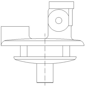
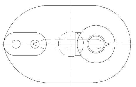
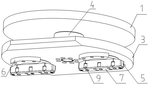
[0027] Embodiment 1: The combined yarn carrier guiding device of the knitting machine of the present invention includes: an upper plate 1, a mandrel 2, a lower plate 3, a rotating sleeve 4, a guide block 5, a guide block supporting plate 6, a guide block bottom plate 7, Roller shaft 8 and roller 9;

[0028] An upper plate 1 and a lower plate 3 are connected to both ends of the mandrel 2, and a rotating sleeve 4 that can rotate freely is sleeved on the mandrel 2 between the upper plate 1 and the lower plate 3; In the hole, there is a guide block 5 that can rotate freely, and the guide block 5 is supported on the lower plate 3 by the guide block supporting plate 6 to prevent the guide block 5 from falling from the lower plate 3; a roller shaft 8 is installed in the guide block 5 , on the roller shaft 8 there are rollers 9 that can rotate freely;

[0029] The center of the upper plate 1 and the lower plate 3 has a mandrel hole, and screw fixing holes uniformly distributed along ...


PUM


Abstract

A combined yarn carrier guiding device of a knitting machine belongs to transmission devices of knitting machines. The combined yarn carrier guiding device comprises an upper plate, a mandrel, a lowerplate, a rotary sleeve, guide blocks, a guide block supporting plate, a guide block bottom plate, roller shafts and rollers. The upper plate and the lower plate are connected with both ends of the mandrel, and the rotary sleeve which can rotate freely is sleeved on the mandrel between the upper plate and the lower plate. Two holes are formed on the lower plate, and the guide blocks which can rotate freely is arranged in the holes. The guide blocks are supported on the lower plate by the guide block supporting plate to prevent the guide blocks from falling off from the lower plate. The rollershafts are arranged in the guide blocks, and the rollers which can rotate freely are arranged on the roller shafts. The guide block bottom plate is connected with the bottom of the guide blocks, and the guide block bottom plate fixes the roller shafts in the guide blocks. The device has the advantages of simple structure, simple processing, high yield, short processing cycle, high reliability, improved production efficiency, reduced production cost, and easy replacement.

Description

technical field [0001] The invention relates to a transmission device of a knitting machine, in particular to a combined yarn carrier guiding device of a knitting machine. Background technique [0002] At present, the structure of the yarn carrier guide device used by people on the knitting machine is as follows: figure 1 , figure 2 shown. [0003] Generally, the guide device of the yarn carrier of the small knitting machine is processed as a whole, because of many processes and the yield rate is not high. As people's demand for knitting products increases, more and larger knitting machines are needed to weave products. This causes the guide device of the yarn carrier to become larger and larger, which brings a lot of trouble to the processing during the processing, resulting in low yield, high manufacturing cost, and long processing cycle; and in the process of use, when the guide device of the yarn carrier is damaged Not easy to replace. Contents of the invention ...

Claims


Application Information

Patent Timeline
Patent Type & Authority Applications(China)
IPC IPC(8): D04C3/00D04C3/48
CPCD04C3/00D04C3/48
Inventor 韩百峰韩金辉仇尊波许雷唐万里韩长江
Owner XUZHOU HENGHUI BRAIDING MACHINE
Why Eureka
Try Eureka