Steel supporting cone-wedge expanded movable end device for collaborative construction of foundation pit groups and construction method thereof

A technology of steel support and foundation pit group, which is applied in basic structure engineering, excavation, construction, etc., can solve the problems of central partition wall load concentration, poor integrity, unreliability, etc., to reduce load concentration and unbalanced, unbalanced distribution. The effect of improvement and reliability assurance

Active Publication Date: 2020-11-13
深圳市交通工程质量监督站 +2
View PDF4 Cites 2 Cited by
  • Summary
  • Abstract
  • Description
  • Claims
  • Application Information

AI Technical Summary

Problems solved by technology

The disadvantages of these two types of active devices are: the steel wedge force transmission method is unreliable, it is easy to cause stress concentration and eccentric force, the nodes are unstable, and the integrity is poor
Especially when the ground soil is soft, the ground at the upper steel support is prone to deformation to the outside of the foundation pit, causing the steel support to loosen and fall off
Another kind of bolt-fastened cone-wedge active end, although it solves the problem of unreliable force transmission method of steel wedge, but the force transmission mechanism is too complicated, and the bearing force of the axial end of the support is partially transmitted to the transverse bolt to bear. The fastening quality requirements are too high, high-strength bolts are required, and some steel materials are demanding, and there are also unreliable factors
None of the above active end devices is suitable for the problem of concentrated and unbalanced loads in the middle partition wall caused by the asymmetric support of adjacent foundation pits in the coordinated construction of foundation pit groups

Method used


Image

  • Steel supporting cone-wedge expanded movable end device for collaborative construction of foundation pit groups and construction method thereof
  • Steel supporting cone-wedge expanded movable end device for collaborative construction of foundation pit groups and construction method thereof

Examples


Embodiment Construction

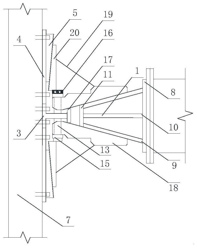
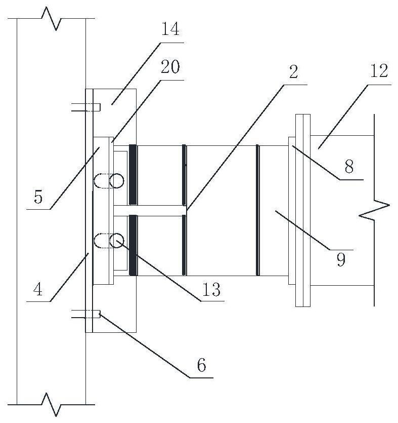
[0019] Attached below figure 1 The technical scheme of the present invention is described in detail:

[0020] A steel-supported cone-wedge extended-type active joint device for coordinated construction of foundation pit groups according to the present invention includes a cone-wedge-shaped support 1 with a flange, an inclined splint 2 with a flange, and a stopper 3 with a jack mounting plate , Stress diffusion bearing plate 4, fixed position plug plate 5, fixed anchor rod 6, ring beam or purlin 7, flange 8, tapered wedge-shaped inclined plate 9, reinforcement plate 10, jack contact plate 11, steel support steel pipe section 12 , Smooth round rod 13, center limiter 14, smooth round rod mount 15, end limiter 16, jack mounting plate 17, inclined splint 18, flange 19, flange supporting plate 20.

[0021] Among them, the center point of the limiter 3 with the jack mounting plate is aligned with the center point of the cone-wedge-shaped support 1 with a flange, so that the load-bea...


PUM


Abstract

The invention is a steel supporting cone-wedge expanded movable end device for collaborative construction of foundation pit groups and a construction method thereof. The center point of a stopper witha jack mounting plate is aligned with the center point of the tapered wedge-shaped support with flange to form a consistent load bearing axis. A flanged cone-wedge support and a steel supporting steel pipe section are connected by flanges. Positioning holes of the inclined splint with flange is passed through a smooth round rod of the stopper with the jack mounting plate. A stress spreading bearing plate is clamped on both sides of the stopper with the jack mounting plate, and anchored to a ring beam or a purlin of a foundation pit enclosure structure through a fixed anchor rod. Supporting column transmits the horizontal force of the flanges with the inclined splint to the ring beam or the purlin of the foundation pit enclosure structure. The device is suitable for the application of thepre-axial force of steel supports and the load spreading of the support end in the coordinated construction of adjacent foundation pits, and reduces the load concentration and imbalance caused by theasymmetric support of the adjacent foundation pits in the coordinated construction of the foundation pit groups.

Description

technical field [0001] The invention relates to a steel-supported cone-wedge extended-type active end device and a construction method for the collaborative construction of foundation pit groups, which is suitable for the application of pre-applied axial force of steel supports and the spread of load at the support end in the collaborative construction of adjacent foundation pits. The asymmetrical support of adjacent foundation pits in the cooperative construction of foundation pit group under the condition of reducing the weakness of the middle pier wall causes the load concentration and unbalance of the end bearing area of ​​the middle partition wall. The utility model belongs to the technical field of foundation pit engineering construction auxiliary workpieces. Background technique [0002] The steel support of foundation pit is widely used in the construction of open excavation method. During the installation of steel support, the application of pre-loaded axial force i...

Claims


Application Information

Patent Timeline
Patent Type & Authority Applications(China)
IPC IPC(8): E02D17/04
CPCE02D17/04
Inventor 张伟马凌宇李洁文郑大轩张天舒魏国平王礼华李富相史豪杰张泽辉
Owner 深圳市交通工程质量监督站
Why Eureka
Try Eureka