
Power telegraph pole erecting device

A technology for pole devices and electric poles, which is applied in the field of electric poles and poles, and can solve problems such as threats to the personal safety of construction workers

Inactive Publication Date: 2020-11-13
STATE GRID SHANDONG ELECTRIC POWER CO PINGYUAN POWER SUPPLY CO
View PDF6 Cites 1 Cited by
  • Summary
  • Abstract
  • Description
  • Claims
  • Application Information

AI Technical Summary

Problems solved by technology

[0004] The object of the present invention is to provide a kind of electric pole pole device, in order to solve the above-mentioned background technology when using the crane pole, if the phenomenon that the rope breaks or loosens, it will bring great harm to the personal safety of the construction workers. threat question

Method used

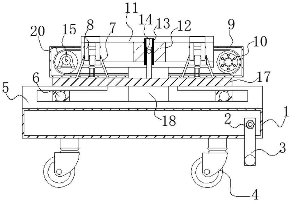
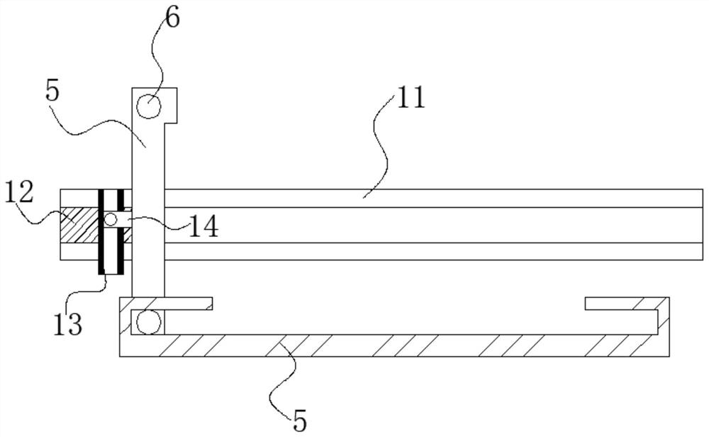

Image

  • Power telegraph pole erecting device
  • Power telegraph pole erecting device
  • Power telegraph pole erecting device

Examples


Embodiment Construction

[0026] Attached below Figure 1-5 , clearly and completely describe the technical solutions in the embodiments of the present invention, obviously, the described embodiments are only some of the embodiments of the present invention, not all of them. Based on the embodiments of the present invention, all other embodiments obtained by persons of ordinary skill in the art without making creative efforts belong to the protection scope of the present invention.

[0027] In describing the present invention, it should be understood that the terms "longitudinal", "transverse", "upper", "lower", "front", "rear", "left", "right", "vertical", The orientations or positional relationships indicated by "horizontal", "top", "bottom", "inner", "outer", etc. are based on the orientations or positional relationships shown in the drawings, and are only for the convenience of describing the present invention, rather than indicating or It should not be construed as limiting the invention by imply...


PUM


Abstract

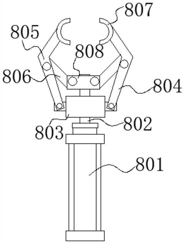
The invention discloses a power telegraph pole erecting device. The telegraph pole erecting device comprises a supporting table, a connecting rod is installed on the side surface of the supporting table, universal wheels are installed at the bottom of the supporting table, a first limiting frame is installed at the top of the supporting table, an overturning plate is installed on the side surfaceof a sliding rod, a supporting rod is installed at the top of the overturning plate, a third movable rod is installed on the side surface of the overturning plate, a sliding plate is installed on theside surface of a third limiting frame, a transmission block is installed on the side surface of the sliding plate, a conveying belt is installed on the side surface of the transmission block in a penetrating mode, a motor is installed on the left side of a transmission shaft, and a supporting column is installed on the right side of the transmission shaft in a deviated mode. Through the arrangement of a clamping device, when a telegraph pole is erected, the telegraph pole only needs to be placed in a clamping ring, then under the action of a hydraulic rod, the first transmission rod enables the clamping ring to form a clamping structure through a first movable rod and a second movable rod so that the telegraph pole can be fixed.

Description

technical field [0001] The invention relates to the technical field of pole uprights, in particular to a pole upright device for electric poles. Background technique [0002] When electricians install electric poles, they need to erect the electric poles so that they can be easily fixed on the ground. Now the pole work of the electric poles is generally done manually, which is not only time-consuming and laborious, but also has a high risk factor. Therefore, in many places, cranes are used to replace manual work on poles, which greatly reduces the labor intensity of construction personnel. [0003] However, when a crane is used to erect a pole, only a few ropes are often used to fix the pole. The construction personnel must stand within the distance between the inverted pole and cooperate with the crane to place the pole upside down. The situation that the rope breaks has taken place, and consequence is unimaginable, for this reason, we propose a kind of electric pole pole ...

Claims


Application Information

Patent Timeline
Patent Type & Authority Applications(China)
IPC IPC(8): E04H12/34
CPCE04H12/345
Inventor 宋洪富路兴平贾翠庆祖林海张玉龙梁晓田忠禹王超王瑞周晓曼
Owner STATE GRID SHANDONG ELECTRIC POWER CO PINGYUAN POWER SUPPLY CO
Learn More