
User-side micro-energy network energy supply system

A user-side, micro-energy technology, applied in the power grid, integrated energy system, and micro-grid field, can solve problems such as difficult to achieve coordination and mutual aid, not conducive to energy efficiency improvement and renewable energy consumption, and limited interconnection, to achieve energy efficiency. The effect of comprehensive utilization

Inactive Publication Date: 2020-11-13
STATE GRID ZHEJIANG ELECTRIC POWER COMPANY TAIZHOU POWER SUPPLY +4
View PDF7 Cites 3 Cited by
  • Summary
  • Abstract
  • Description
  • Claims
  • Application Information

AI Technical Summary

Problems solved by technology

The distributed energy system provides an effective way for commercial or industrial users who need cold, heat, and electricity, as well as island power supply and mobile power supply, but the energy utilization method of the distributed energy system is distributed "on-site collection, on-site storage, use", it is difficult to achieve coordination and mutual aid in a certain area
On the other hand, in the traditional energy system, different energy industries such as power supply, heating, and cooling are relatively closed, and the degree of interconnection is limited. Different systems are planned and operated in isolation, which is not conducive to the improvement of energy efficiency and the consumption of renewable energy.

Method used


Image

  • User-side micro-energy network energy supply system
  • User-side micro-energy network energy supply system
  • User-side micro-energy network energy supply system

Examples


Embodiment Construction

[0033] The following will clearly and completely describe the technical solutions in the embodiments of the present invention with reference to the accompanying drawings in the embodiments of the present invention. Obviously, the described embodiments are only some, not all, embodiments of the present invention. The following description of at least one exemplary embodiment is merely illustrative in nature and in no way taken as limiting the invention, its application or uses. Based on the embodiments of the present invention, all other embodiments obtained by persons of ordinary skill in the art without creative efforts fall within the protection scope of the present invention.

[0034] Those skilled in the art can understand that, under the condition of no conflict, the features in the following embodiments and implementation manners can be combined with each other.

[0035] A user-side micro-energy grid energy supply system. Among them, the typical structural form of the m...


PUM


Abstract

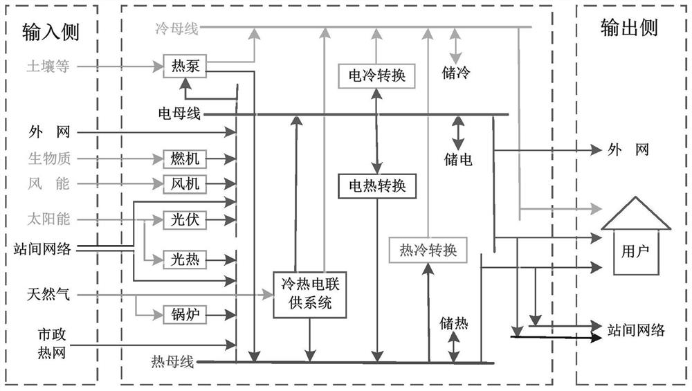
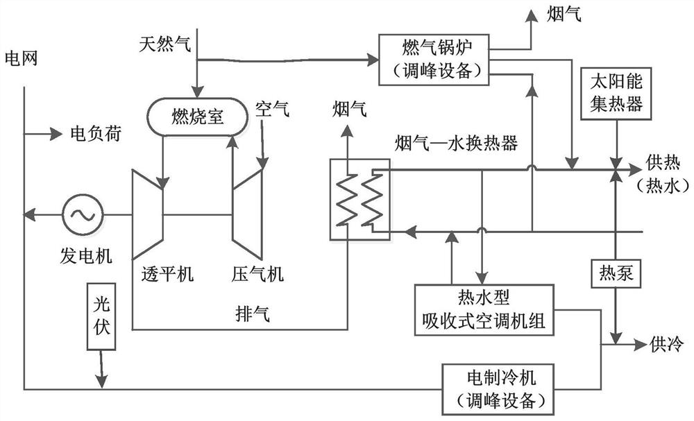
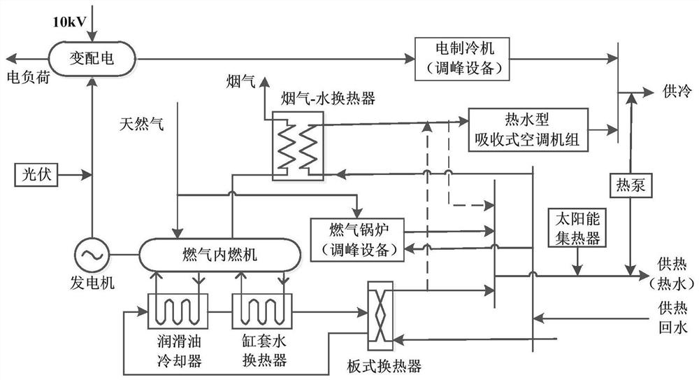
The invention discloses a user-side micro-energy network energy supply system. The user-side micro-energy network energy supply system comprises a residential community micro-energy network, a commercial park micro-energy network, an industrial area micro-energy network and an agricultural area micro-energy network, wherein each of the residential community micro-energy network, the commercial park micro-energy network, the industrial area micro-energy network and the agricultural area micro-energy network comprises an input unit, an intermediate energy production, conversion and storage unitand an output unit; the input unit is connected with an external power grid, a municipal heat supply network and a natural gas network, is also connected with other micro-energy networks, and inputs electric energy and heat energy of the other micro-energy networks; the intermediate energy production, conversion and storage unit comprises a cold bus, a heat bus, an electric bus, an energy conversion device and an energy storage device; and the output unit outputs cold, heat and electricity to meet cold, heat and electricity requirements of users in the micro-energy networks, redundant electricity is connected to the networks or is supplied to the other micro-energy networks, and redundant heat energy is supplied to the other micro-energy networks. The user-side micro-energy network energysupply system can realize clean and efficient, energy-saving and environment-friendly gradient utilization, complementary coordination, safety and high quality of the whole process of energy production, transmission and utilization.

Description

technical field [0001] The invention belongs to the technical field of power grids, and in particular relates to the technical fields of micro-grids and comprehensive energy systems. Background technique [0002] my country is facing an "energy comprehensive era" in which new energy and fossil energy complement each other. Under the energy demand in the new era, my country urgently needs to take a new round of technological revolution and industrial revolution as the fulcrum, and change from the previous extensive development model to a more intensive one. , sustainable development model, and establish a more efficient, safe and sustainable energy utilization model. The distributed energy system provides an effective way for commercial or industrial users who need cold, heat, and electricity, as well as island power supply and mobile power supply, but the energy utilization method of the distributed energy system is distributed "in-situ collection, on-site storage, on-site U...

Claims


Application Information

Patent Timeline
IPC IPC(8): F24D10/00F24D11/02F24F5/00F24F13/30
CPCF24D10/003F24D11/0221F24D11/0242F24F5/0046F24F13/30Y02B30/17
Inventor 张宏达周灵江王帅李剑秦建张永华陈鑫谢建华王振林卫敏丁小洪郭锦卫朱超李万里徐建伟周静雷翔宇
Owner STATE GRID ZHEJIANG ELECTRIC POWER COMPANY TAIZHOU POWER SUPPLY
Learn More