
Ultrasonic detection 3D imaging analysis method

A technology of ultrasonic detection and analysis method, which is applied to the analysis of solids using sound waves/ultrasonic waves/infrasonic waves, material analysis and material analysis using sound waves/ultrasonic waves/infrasonic waves, etc. Observe the distribution and other issues

Pending Publication Date: 2020-11-13
GUANGDONG GOWORLD
View PDF3 Cites 0 Cited by
  • Summary
  • Abstract
  • Description
  • Claims
  • Application Information

AI Technical Summary

Problems solved by technology

The projection view may cause some defects to overlap and cover, and it is impossible to quickly observe the distribution of each defect, which may easily lead to missed detection or misjudgment

Method used


Image

  • Ultrasonic detection 3D imaging analysis method
  • Ultrasonic detection 3D imaging analysis method
  • Ultrasonic detection 3D imaging analysis method

Examples


Embodiment Construction

[0023] The present invention will be specifically described below in conjunction with specific embodiments.

[0024] The ultrasonic detection 3D imaging analysis method in the present embodiment comprises the following steps:

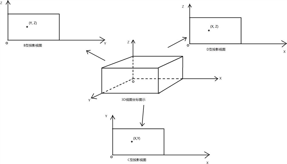
[0025] (1) if figure 1 As shown, the space Cartesian coordinate system O-XYZ is established, and the 3D view of the ultrasonic detection 3D imaging is projected according to the three-view method, and the B-type projection view is the plane YOZ, the C-type projection view is the plane XOY, and the D-type projection view is the plane XOZ;

[0026] (2) Set the cross cursor (X, Y, Z) used to measure the position in the B-type projection view, C-type projection view, and D-type projection view. The position value of the cross cursor in the B-type projection view is expressed as (Y , Z), the position value of the cross cursor in the C-type projection view is expressed as (X, Y), and the position value of the cross cursor in the D-type projection view is ex...


PUM


Abstract

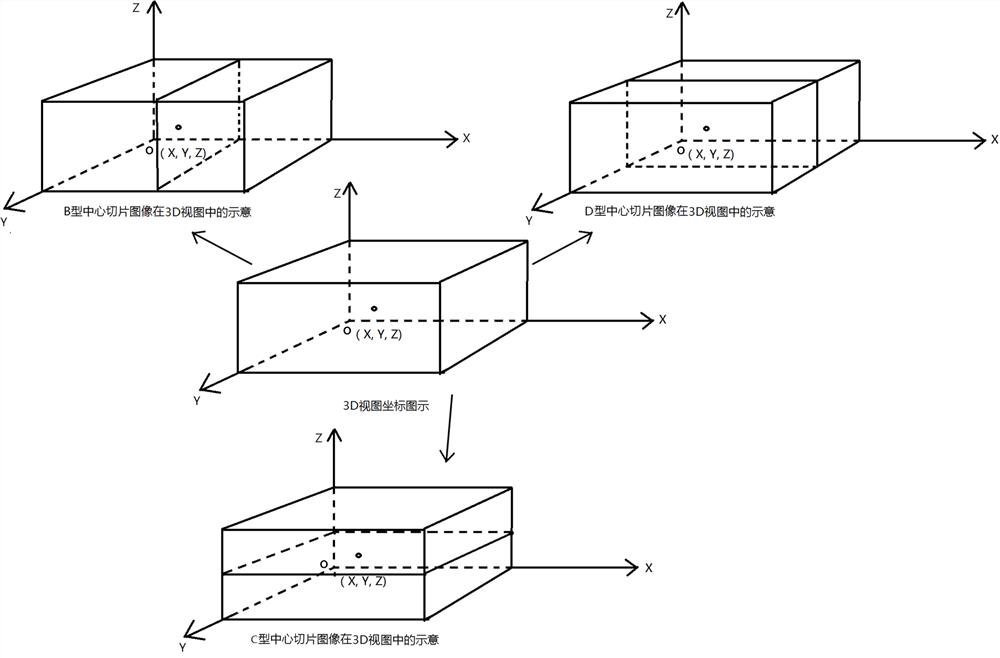
The invention discloses an ultrasonic detection 3D imaging analysis method. According to the ultrasonic detection 3D imaging analysis method, B-type projection views, C-type projection views, D-type projection views, B-type slice images, C-type slice images and D-type slice images are carried out on 3D views to carry out automatic measurement analysis and quantification on defects in 3D images; adetector can quickly analyze the generated whole 3D image, quickly observe the distribution condition of each defect in the 3D image, avoid missing detection and misjudgment, and can be applied to thefield of nondestructive detection.

Description

technical field [0001] The invention relates to the technical field of ultrasonic nondestructive testing, in particular to a 3D imaging analysis method for ultrasonic testing. Background technique [0002] Ultrasound imaging is currently the method of obtaining visible images of objects using ultrasound waves. Since ultrasonic waves can penetrate many opaque objects, ultrasonic waves can be used to obtain information on the acoustic properties of the internal structures of these objects. Ultrasonic imaging technology turns these information into images visible to the human eye. Ultrasonic imaging of objects can provide a large amount of intuitive information, directly display the internal conditions of the object, and has high reliability and reproducibility, and can perform quantitative and dynamic monitoring of defects. At present, the commonly used ultrasonic imaging detection display methods in the field of non-destructive testing include B-type projection display, C-ty...

Claims


Application Information

Patent Timeline
Patent Type & Authority Applications(China)
IPC IPC(8): G01N29/06
CPCG01N29/069G01N29/0645
Inventor 付汝龙杨贵德詹红庆杜南开陈振光林齐梅林丹源陈建华曾庆勋
Owner GUANGDONG GOWORLD
Learn More