AC resistance detection circuit and system

A technology of AC resistance and detection circuit, which is applied in the direction of measuring resistance/reactance/impedance, measuring devices, and measuring electrical variables, etc. It can solve the problems of increasing error probability and troubles for users, so as to achieve ease of use, improve system reliability, and improve The effect of customer experience

Active Publication Date: 2020-11-13
SHANGHAI NATLINEAR ELECTRONICS CO LTD
View PDF6 Cites 1 Cited by
  • Summary
  • Abstract
  • Description
  • Claims
  • Application Information

AI Technical Summary

Problems solved by technology

[0005] In view of the above-mentioned shortcomings of the prior art, the object of the present invention is to provide an AC resistance detection circuit and system, which is used to solve the problem of strictly distinguishing between the neutral wire and the live wire when two detection circuits are connected in parallel to the power grid in the prior art, and then Problems that cause trouble for users and increase the probability of error

Method used


Image

  • AC resistance detection circuit and system
  • AC resistance detection circuit and system
  • AC resistance detection circuit and system

Examples


Embodiment 1

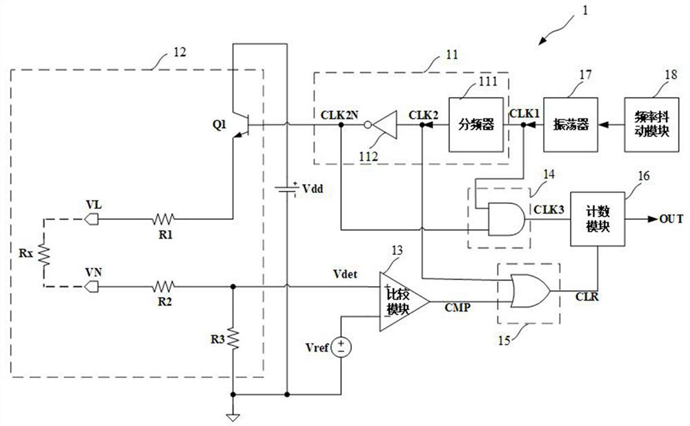
[0040] Such as figure 1 As shown, this embodiment provides an AC resistance detection circuit 1, and the AC resistance detection circuit 1 includes:

[0041] Working state control module 11 , sampling module 12 , comparison module 13 , counting signal generating module 14 , clearing module 15 and counting module 16 .

[0042] Such as figure 1 As shown, the working state control module 11 receives the oscillating signal CLK1 and generates the working state control signal CLK2N to control the working state to alternately switch between the detection state and the waiting state in sequence.

[0043] Specifically, in this embodiment, the working state control module 11 includes a frequency divider 111 and an inverter 112 . The frequency divider 111 receives the oscillating signal CLK1 and divides the frequency of the oscillating signal CLK1 . As an example, the frequency divider is used to realize frequency division by sixteen. The inverter 112 is connected to the output termin...

Embodiment 2

[0085] Such as Figure 5 As shown, this embodiment provides an AC resistance detection system, and the AC resistance detection system includes:

[0086] Two AC resistance detection circuits; wherein, the first terminal VLa of the first AC resistance detection circuit 1a is connected to the neutral line N, and the second terminal VNa is connected to the live line L; the first terminal VLb of the second AC resistance detection circuit 1b is connected to the live line L, The second terminal VNb is connected to the neutral line N. The first AC resistance detection circuit 1a and the second AC resistance detection circuit 1b adopt the structure of the AC resistance detection circuit of the first embodiment.

[0087] Such as Figure 5 As shown, when the zero line and live line of the first AC resistance detection circuit 1a and the second AC resistance detection circuit 1b are reversely mixed, and there is no other resistance between the AC live line and the neutral line, an AC re...

Embodiment 3

[0098] This embodiment provides an AC resistance detection system, and the AC resistance detection system includes:

[0099] Two AC resistance detection circuits; wherein, the first end of the first AC resistance detection circuit is connected to the neutral wire, and the second end is connected to the live wire; the first end of the second AC resistance detection circuit is connected to the neutral wire, and the second end is connected to the live wire.

[0100] Specifically, the first AC resistance detection circuit and the second AC resistance detection circuit adopt the structure of the AC resistance detection circuit in Embodiment 1. At this time, since the live wires and neutral wires of the two AC resistance detection circuits are not mixed, Therefore, the current in the first AC resistance detection circuit will not flow into the second AC resistance detection circuit, and the current in the second AC resistance detection circuit will not flow into the first AC resistan...


PUM


Abstract

The invention provides an AC resistance detection circuit and system. The circuit comprises a working state control module which generates a working state control signal so as to achieve the sequential and alternate switching between a detection state and a waiting state, a sampling module which is used for outputting a sampling signal of a resistor between the zero line and the live line in a detection state, a comparison module which is used for receiving the reference signal and the sampling signal and outputting a comparison result, a counting signal generation module which is used for receiving the oscillation signal and the working state control signal and outputting the oscillation signal as a counting signal in a detection state, a zero clearing module which is used for receiving the comparison result and the working state control signal and outputting an effective zero clearing signal when the resistance between the zero line and the live wire is greater than a threshold value, and a counting module which is connected with the counting signal and the zero clearing signal and outputs a high level when the counting value reaches a preset value. According to the circuit, whenzero line and live line access ends are reversely connected in a mixed manner and no other resistor exists between the alternating current live line and the zero line, an output signal is not wrong,and system reliability is improved.

Description

technical field [0001] The invention relates to the field of circuit design, in particular to an AC resistance detection circuit and system. Background technique [0002] In many applications, we need to detect the power supply status of the AC power supply. The prior art is realized by detecting the resistance between the neutral wire and the live wire of the AC grid. Only when the detection circuit detects that the resistance between the neutral wire and the live wire is less than a certain threshold value, the AC grid is considered to be in a blackout state. [0003] When using the existing AC resistance detection circuit, it is necessary to distinguish the neutral wire and the live wire. If two detection circuits are connected in parallel to the AC power grid, and the neutral wire and the live wire are cross-connected, it may cause the current output by one detection circuit to enter the other detection circuit, causing the detection circuit to output a wrong detection...

Claims


Application Information

Patent Timeline
IPC IPC(8): G01R27/02
CPCG01R27/02
Inventor 夏虎吴春达王冬峰刘桂芝
Owner SHANGHAI NATLINEAR ELECTRONICS CO LTD
Why Eureka
Try Eureka