Unmanned aerial vehicle target tracking system and method based on machine vision

A machine vision and target tracking technology, applied in the field of drones, can solve problems such as affecting target tracking and the impact of drones

Inactive Publication Date: 2020-11-13
NANJING COREWELL CLOUD COMPUTING INFORMATION TECH CO LTD
View PDF0 Cites 3 Cited by
  • Summary
  • Abstract
  • Description
  • Claims
  • Application Information

AI Technical Summary

Problems solved by technology

[0005] The purpose of the present invention is to provide a UAV target tracking system based on machine vision to solve the problem that the disturbance and time lag are increasingly affecting the UAV with the increase of the single flight time of the UAV proposed in the background technology. Big, problem that affects target tracking

Method used


Image

  • Unmanned aerial vehicle target tracking system and method based on machine vision
  • Unmanned aerial vehicle target tracking system and method based on machine vision
  • Unmanned aerial vehicle target tracking system and method based on machine vision

Examples


Embodiment Construction

[0048] The following will clearly and completely describe the technical solutions in the embodiments of the present invention with reference to the accompanying drawings in the embodiments of the present invention. Obviously, the described embodiments are only some, not all, embodiments of the present invention.

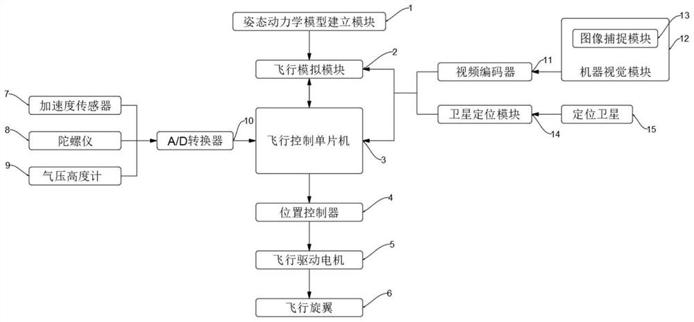
[0049] see Figure 1-2 , an embodiment provided by the present invention: the UAV target tracking system based on machine vision, including a flight control single-chip microcomputer 3, the flight control single-chip microcomputer 3 is connected with the flight simulation module 2 two-way data, and the flight control single-chip microcomputer 3 feeds back to the flight simulation module 2 The actual flight data, the flight simulation module 2 sends the simulated flight data to the flight control single-chip microcomputer 3, the flight control single-chip microcomputer 3 flies according to the simulated value, the input end of the flight simulation module 2 is connecte...


PUM


Abstract

The invention discloses an unmanned aerial vehicle target tracking system and method based on machine vision, relates to the related field of unmanned aerial vehicles, and aims at solving the problemsthat in the prior art, disturbance and time lag have more and more influences on an unmanned aerial vehicle along with increase of single flight time of the unmanned aerial vehicle, and the target tracking is influenced. A flight control single-chip microcomputer is in bidirectional data connection with the flight simulation module. The input end of a flight simulation module is connected with the output end of an attitude dynamics model establishing module. The input end of the flight control single-chip microcomputer is connected with the output end of the A/D converter. The input end of the A/D converter is respectively connected with the output ends of an acceleration sensor, a gyroscope and a barometric altimeter; the output end of the flight control single-chip microcomputer is connected with the input end of a position controller, the output end of the position controller is connected with the input end of a flight driving motor, and the output end of the flight driving motor is connected with the input ends of flight rotors.

Description

technical field [0001] The invention relates to the field of unmanned aerial vehicles, in particular to an unmanned aerial vehicle target tracking system based on machine vision. Background technique [0002] Machine vision is a rapidly developing branch of artificial intelligence. Simply put, machine vision is the use of machines instead of human eyes for measurement and judgment. The machine vision system converts the captured target into an image signal through the machine vision product (that is, the image capture device, which is divided into CMOS and CCD), and transmits it to a dedicated image processing system to obtain the shape information of the captured target. According to the pixel distribution and Information such as brightness and color is converted into digital signals; the image system performs various operations on these signals to extract the characteristics of the target, and then controls the on-site equipment actions according to the results of the dis...

Claims


Application Information

Patent Timeline
Patent Type & Authority Applications(China)
IPC IPC(8): G05D1/12
CPCG05D1/12
Inventor 段纳苗珍张正强孟国华张金慧管连勇
Owner NANJING COREWELL CLOUD COMPUTING INFORMATION TECH CO LTD
Why Eureka
Try Eureka