Intelligent switch cabinet with infrared temperature measurement window
A smart switch and infrared temperature measurement technology, applied in the field of switch cabinets, can solve the problems of inconvenient operation and low intelligence, and achieve the effect of eliminating potential safety hazards and improving convenience
- Summary
- Abstract
- Description
- Claims
- Application Information
AI Technical Summary
Problems solved by technology
Method used
Image

Examples
Embodiment
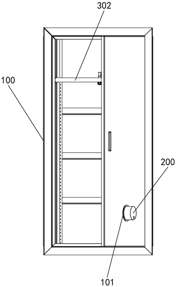
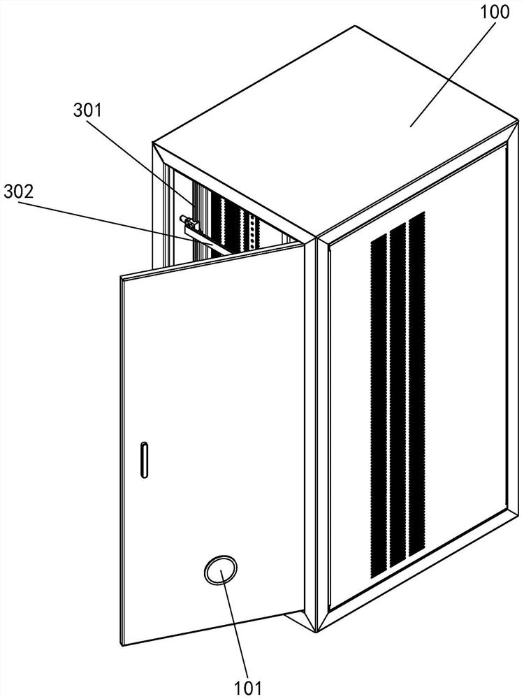
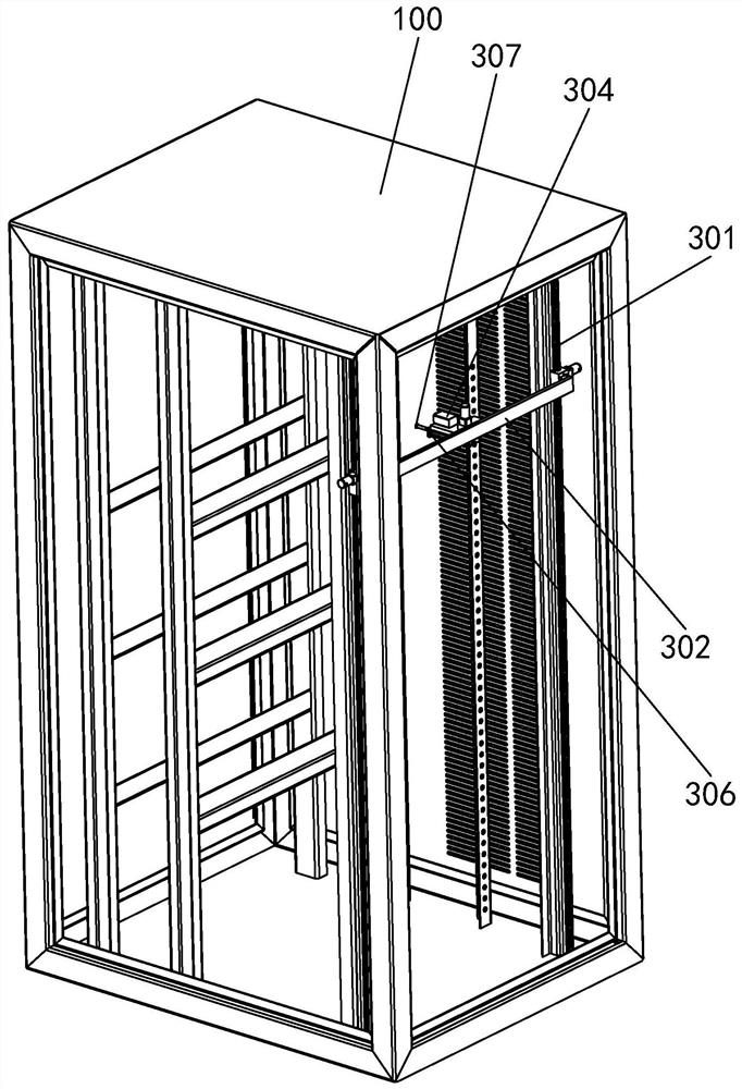
[0027] Example: see Figure 1-5 , an intelligent switch cabinet with an infrared temperature measurement window, a door panel 101 is installed on the front side of the intelligent switch cabinet 100, an infrared temperature measurement window 101 is provided on the outside of the door panel 101, and a wireless PLC controller is installed in the intelligent switch cabinet 100, An infrared temperature sensor 200 is detachably installed on the outside of the infrared temperature measurement window 101, and the detection end of the infrared temperature sensor 200 is facing the infrared temperature measurement window 101; the temperature measurement window of the infrared temperature measurement window 101 is a quartz glass window, and the infrared temperature sensor 200 adopts SIN-AL-10 type, the infrared temperature sensor 200 is installed on a bracket, and the bracket is detachably fixed on the door panel 101 by screws. The detection end of the infrared temperature sensor 200 is ...
PUM
 Abstract
Description
Claims
Application Information
 - R&D
- Intellectual Property
- Life Sciences
- Materials
- Tech Scout
- Unparalleled Data Quality
- Higher Quality Content
- 60% Fewer Hallucinations
Browse by: Latest US Patents, China's latest patents, Technical Efficacy Thesaurus, Application Domain, Technology Topic, Popular Technical Reports.
© 2025 PatSnap. All rights reserved.Legal|Privacy policy|Modern Slavery Act Transparency Statement|Sitemap|About US| Contact US: help@patsnap.com