A compression hemostasis device for cardiology

A technique of cardiology and hemostatic cotton is applied in the field of pressing hemostatic devices, which can solve the problems of bleeding at the puncture end, increase cumbersomeness, and blood flow to other parts of the body, and achieve the effects of reducing air residue, reducing bacteria content, and reducing cumbersomeness.

Active Publication Date: 2022-05-20
王霞霞
View PDF10 Cites 0 Cited by
  • Summary
  • Abstract
  • Description
  • Claims
  • Application Information

AI Technical Summary

Problems solved by technology

[0002] The Department of Cardiology, that is, the Department of Cardiovascular Medicine, is a clinical department set up by the major internal medicine departments of hospitals at all levels for the diagnosis and treatment of cardiovascular and vascular diseases. The diseases treated include angina pectoris, hypertension, sudden death, arrhythmia, heart failure, premature beats, arrhythmia, For myocardial infarction, cardiomyopathy, myocarditis, acute myocardial infarction and other cardiovascular diseases, the cardiology department will use nurses to independently collect dynamic and static blood. Dredging treatment, but the use of interventional treatment also has certain defects, mainly because bleeding at the puncture end is prone to occur when the catheter guide wire is removed after treatment
[0003] When the existing pressing hemostatic device is in use, the hemostatic cotton is pressed on the bleeding site, and the hemostatic cotton is fixed to complete the hemostasis of the affected area. However, due to the bacteria in the affected area entering the blood, the above method cannot guarantee that the affected area will be polluted. The blood is discharged in time, and the blood that is easy to cause pollution flows to other parts of the body after hemostasis, and the affected area needs to be continuously disinfected and sterilized. While the safety cannot be guaranteed, it increases the cumbersomeness of the follow-up treatment

Method used


Image

  • A compression hemostasis device for cardiology
  • A compression hemostasis device for cardiology
  • A compression hemostasis device for cardiology

Examples


Embodiment Construction

[0025] In order to make the purposes, technical solutions and advantages of the embodiments of the present invention clearer, the technical solutions in the embodiments of the present invention will be clearly and completely described below with reference to the accompanying drawings in the embodiments of the present invention. Obviously, the described embodiments These are some embodiments of the present invention, but not all embodiments. Based on the embodiments of the present invention, all other embodiments obtained by those of ordinary skill in the art without creative efforts shall fall within the protection scope of the present invention.

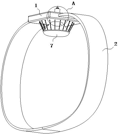
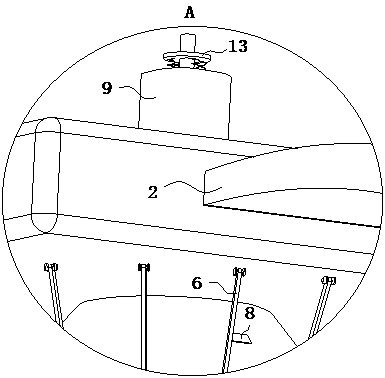
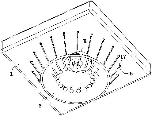
[0026] The present invention provides such as Figure 1-6 The shown pressure hemostasis device for cardiology includes a pressing plate 1 and straps 2 connected on both sides of the pressing plate 1. The bottom of the pressing plate 1 is connected with a circular truncated cover 3, and the inner side of the circular truncated cover ...


PUM


Abstract

The invention discloses a compression hemostasis device used in cardiology, which comprises a compression covering plate and straps connected on both sides thereof. No. 1 connecting rods, the bottom ends of multiple No. 1 connecting rods are gradually approaching the vertical line of the bottom surface of the pressure cladding plate, and the bottom ends of the No. 1 connecting rods are connected with tightening balls; the present invention presses the pressure cladding plate on the affected part, and multiple The tightening balls will be squeezed and close to each other, and then the blood around the affected area will be pushed to the affected area during the movement of the tightening balls, so that the contaminated blood will be soaked from the affected area to the hemostatic cotton, while the tightening balls will be While pressing and moving, the No. 2 connecting rod will push the bottom of the conical cover close to the tightening ball, and the bottom of the conical cover will further push the blood around the affected area out of the affected area. By moving the tightening ball and the conical cover, the affected area can be The peripheral blood is pressed out, which improves the safety after hemostasis and reduces the cumbersomeness of follow-up treatment.

Description

technical field [0001] The invention belongs to the technical field of medical equipment, and in particular relates to a compression hemostasis device for cardiology. Background technique [0002] Cardiology, namely cardiovascular medicine, is a clinical department set up by major internal medicine departments of hospitals at all levels for the diagnosis and treatment of cardiovascular and vascular diseases. The diseases treated include angina pectoris, hypertension, sudden death, arrhythmia, heart failure, premature beats, arrhythmia, Cardiovascular diseases such as myocardial infarction, cardiomyopathy, myocarditis, acute myocardial infarction, etc., the cardiology department will use nurses to complete the collection of dynamic and static blood independently. The dredging treatment, but the interventional treatment also has certain defects, mainly because the bleeding at the puncture end is prone to occur when the catheter guide wire is removed after treatment. [0003] ...

Claims


Application Information

Patent Timeline
Patent Type & Authority Patents(China)
IPC IPC(8): A61B17/132A61M35/00
CPCA61B17/1325A61M35/10A61B2017/12004
Inventor 王霞霞于淑萍周田田
Owner 王霞霞
Why Eureka
Try Eureka