
Atrial septum puncture assembly

An atrial septum and component technology, which is applied in the medical field, can solve the problem of not being able to judge the distance between the tip of the dilating sheath and the atrium of the heart and the safety of puncture, and achieve the effect of preventing cardiac perforation.

Active Publication Date: 2020-11-17
HARBIN MEDICAL UNIVERSITY
View PDF6 Cites 0 Cited by
  • Summary
  • Abstract
  • Description
  • Claims
  • Application Information

AI Technical Summary

Problems solved by technology

[0005] The present invention provides an atrial septal puncture assembly due to the problem of puncture safety due to the inability to judge the distance between the tip of the expansion sheath and the atrium at any time during atrial septal puncture

Method used


Image

  • Atrial septum puncture assembly
  • Atrial septum puncture assembly
  • Atrial septum puncture assembly

Examples


Embodiment 1

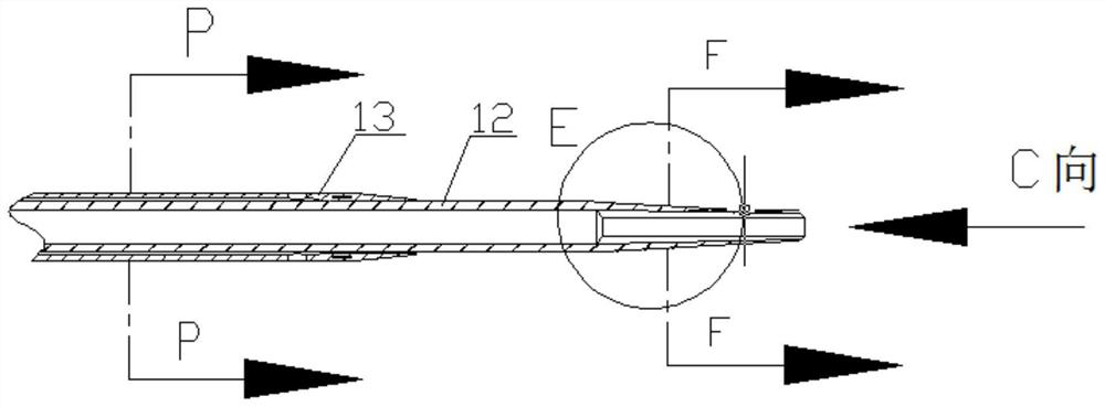
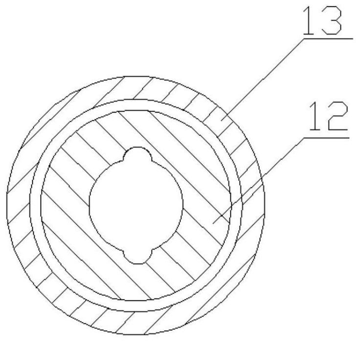
[0051] Such as Figure 1 to Figure 7As shown, the atrial septal puncture assembly 10 includes an atrial septal puncture needle 11 , a dilator 12 and a sheath 13 . Wherein the dilator includes a dilator tube body, the dilator tube body includes a distal end, a proximal end and a central chamber, and a dilator side tube 44 and a three-way valve 15 are provided at the proximal end of the dilator tube body. At least one groove 23 is provided on the inner wall of the distal chamber of the dilator body. There may also be two or more grooves, which can be determined by those skilled in the art according to actual needs. One end of the groove reaches directly to the tip of the dilator, and the other end can extend to the proximal end of the dilator body and connect to a three-way valve through a side tube. The contrast agent flows along the grooves to the end of the dilator tube where it is ejected. A tube body may also be provided in the groove, and the contrast agent flows along ...

Embodiment 2

[0054] Such as Figure 8 to Figure 13 As shown, the atrial septal puncture assembly 10 includes an atrial septal puncture needle 11 , a dilator 12 and a sheath 13 . Wherein the dilator includes a dilator tube body, the dilator tube body includes a distal end, a proximal end and a central chamber, and a dilator side tube joint 14 is provided at the proximal end of the dilator tube body. At least one groove 23 is provided on the inner wall of the distal chamber of the dilator body. There may also be two or more grooves, which can be determined by those skilled in the art according to actual needs. The groove described in this example does not extend to the proximal end of the dilator body, so there is no side tube at the proximal end of the dilator. The widest part of the groove is larger than the outer diameter of the tube body of the interseptal puncture needle. The contrast agent flows along the grooves to the end of the dilator tube where it is ejected.

[0055] A tube b...


PUM


Abstract

The invention discloses an atrial septum puncture assembly, relates to the field of medicine, and aims to solve the problem of puncture safety caused by the fact that the distance between the tip of an expansion sheath and an atrium cannot be judged at any time in atrial septum puncture. The atrial septum puncture assembly comprises an atrial septum puncture needle, an expander and a sheath tube,wherein the expander comprises an expander tube body; the expander tube body comprises a far end, a near end and a central chamber; the near end of the expander tube body can be provided with an expander side tube and is connected with a three-way joint; the inner wall of the chamber of the expander tube body is provided with at least one groove; and the groove directly reaches the tip of the farend of the expander. According to the scheme, in an atrial septum puncture operation, when a contrast agent or heparin normal saline is injected, the contrast agent or the heparin normal saline can besprayed out from the tip of the expander, and the position of the far end of the expander can be clearly judged under X rays or intracardiac ultrasound. The atrial septum puncture assembly is appliedto the field of atrial septum puncture.

Description

technical field [0001] The invention relates to the medical field, in particular to an atrial septum puncture assembly. Background technique [0002] At present, with the rapid development of interventional equipment and equipment, the application of cardiac interventional therapy is becoming more and more extensive, which makes atrial septal puncture more widely used. In 1959, Ross et al. reported the animal experimental study of atrial septal puncture, and in the same year, Cope and Rossdeng et al first applied atrial septal puncture to clinic. In the early atrial septal puncture, the method of directly puncturing the atrial septum with a puncture needle through the right atrial catheter was used. In 1960, Brockenbrough and Brawnwald et al. The tapered structure at the end increases the safety of operation. In 1977, Mullins et al. configured an outer sheath for the atrial septal puncture catheter, which further improved the operability and safety of atrial septal punctur...

Claims


Application Information

Patent Timeline
Patent Type & Authority Applications(China)
IPC IPC(8): A61B17/34
CPCA61B17/34A61B17/3403A61B2017/3413
Inventor 王召军
Owner HARBIN MEDICAL UNIVERSITY
Learn More