Clinical medical drainage device

A drainage tube and drainage bag technology, which is applied in the field of clinical medical drainage devices, can solve the problems of increasing the burden on medical staff and patients' families, failing to follow the doctor's expected method, and difficult to guarantee the drainage effect, etc., so as to improve safety and stability, Drainage effect guarantee, effect of reducing work load

Inactive Publication Date: 2020-11-17
德州飚丰信息技术有限公司
View PDF0 Cites 2 Cited by
  • Summary
  • Abstract
  • Description
  • Claims
  • Application Information

AI Technical Summary

Problems solved by technology

[0004] In the clinical operation of drainage of a large amount of effusion, there are often specific requirements for clinical parameters such as daily drainage times, each drainage volume, and drainage speed according to the condition of the case. The parameters are usually controlled subjectively by the medical staff or the patient's family members. The current artificial control method has certain disadvantages. As a result, the drainage process cannot be carried out in the way the doctor expected, and the improper drainage will cause discomfort and injury to the patient, and even endanger the patient's life. On the other hand, the real-time drainage volume and drainage speed during the drainage process are usually determined by human observation. Judgment, the error is large, and it is difficult to guarantee the drainage effect. At the same time, the current control method will obviously increase the burden on the medical staff and the patient's family members.
[0005] The drainage bag is a relatively cheap medical product, and it is the best choice as the terminal container in clinical effusion drainage, but it can only be applied to conventional pleural effusion drainage operations under normal pressure, and cannot be applied to negative pressure drainage. Negative pressure drainage usually requires the use of water-sealed bottles that are more expensive than drainage bags, which brings a certain economic burden to patients

Method used


Image

  • Clinical medical drainage device
  • Clinical medical drainage device
  • Clinical medical drainage device

Examples


Embodiment 1

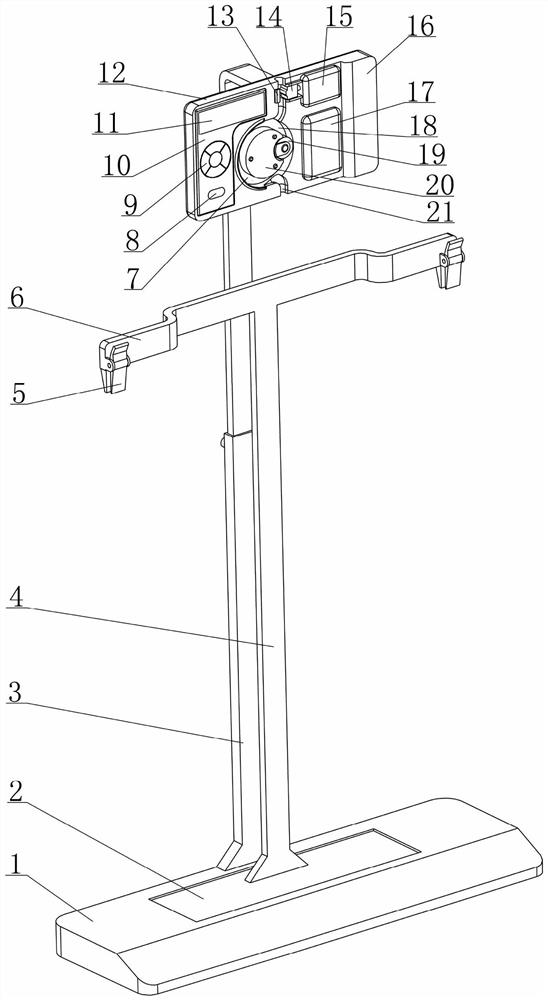
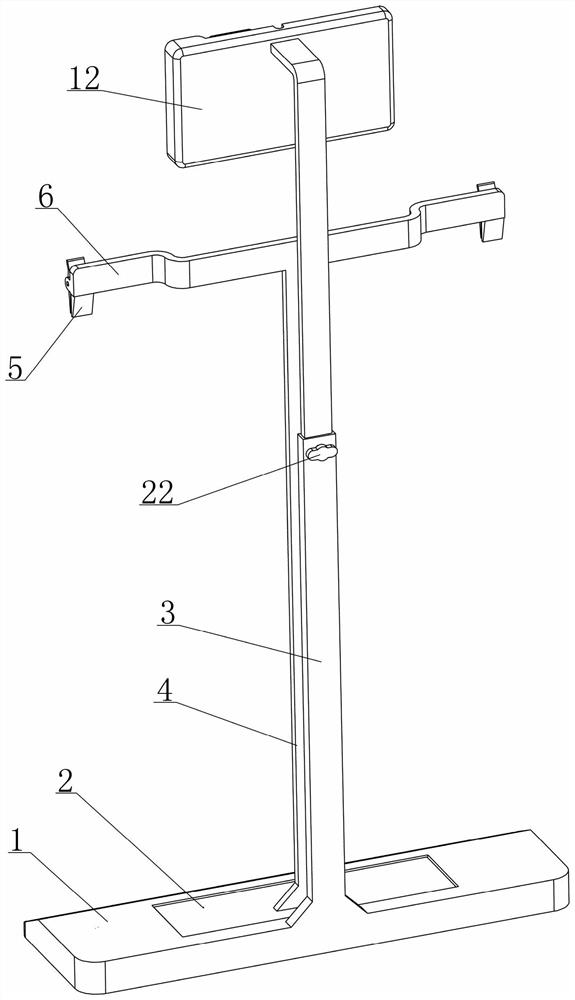
[0042] see figure 1 , 2 As shown, a clinical medical drainage device disclosed in this embodiment is composed of a weighing base assembly, a suspension assembly, a seat assembly, a flow rate adjustment mechanism, a negative pressure drainage mechanism, a controller 10 and a power supply assembly 16. Partial composition;

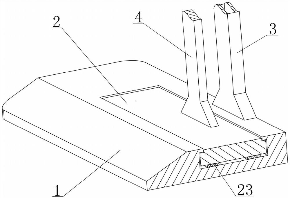
[0043] Among them, see figure 1 , 3 As shown, the weighing base assembly is composed of a weighing platform 2, a weighing sensor 23 and a base 1 that are sequentially matched up and down, and the weighing sensor 23 outputs a weighing signal that can reflect the weight of the object above the weighing platform 2;

[0044] Among them, see figure 1 , 5 As shown in . The support beam 6 is provided with a clip 5 for clamping the top of the drainage bag 28, and the suspension assembly is used to hang the drainage bag 28 directly above the weighing platform 2, so as to ensure that the weight of the drainage bag 28 and its internal fluid tends to All the indir...

Embodiment 2

[0076] In the clinical medical drainage device disclosed in embodiment 1, such as Figure 8 As shown, the driving device 15 can drive the movable clamp block 14 to move the position based on the control of the controller 10, and adjust the extrusion state of the movable clamp block 14 to the drainage tube 27. As far as this technical feature is concerned, the driving device 15 adopts the prior art There are many implementations, but in order to make the structure of the driving device 15 simpler and more compact and to adjust the position of the movable clamp block 14 more accurately, this embodiment provides a driving device 15 with a simple structure and stable operation. The structure is as follows:

[0077] see Figure 12 As shown, the driving device 15 includes a motor 33 fixed on the mounting plate 12, the output shaft of the motor 33 is coaxially connected with a screw 32, the movable clamping block 14 is provided with a screw hole 31, and the movable clamping block 14...

Embodiment 3

[0080] see Figure 8 , 10 As shown, in the clinical use of the clinical medical drainage device disclosed in Embodiment 1, each time the drainage is suspended, ended or the entire drainage operation is completed, the drainage tube 27 is controlled by the movable clamp block 14 and the fixed clamp block 13 in the flow rate adjustment mechanism. Extruded and blocked state, at this time, if the drainage tube 27 is to be separated from the placement groove 21 as a whole, it is necessary to adjust the position of the movable clamp block 14 with the help of the switch key 8, so that the flow rate adjustment mechanism releases the pressure on the drainage tube 27. However, if any component in the switch key 8, the controller 10, the power supply and the driving device 15 fails, the movable clamp block 14 cannot move as expected, so that the drainage tube 27 cannot be smoothly removed from the placement groove. separated in 21;

[0081] Considering that the above defects bring certa...


PUM


Abstract

The invention relates to the field of medical instruments, and discloses a clinical medical drainage device. The clinical medical drainage device comprises a weighing type base assembly, a suspensionsupport assembly, a placement seat assembly, a flow speed adjusting mechanism and a negative pressure drainage mechanism. The weighing type base assembly can feed back a weight signal to a controller.A placement groove capable of clamping and fixing the middle lower part of a drainage tube is formed in the placement seat assembly. The flow speed adjusting assembly can extrude the drainage tube todifferent degrees under the control of the controller so as to achieve the purpose of adjusting the flow speed of fluid in the drainage tube. The negative pressure drainage mechanism can gradually drive the drainage tube to output fluid under the control of the controller so as to achieve negative pressure drainage. According to the clinical medical drainage device, intelligent design is adopted,automatic control over timing drainage, quantitative drainage and constant-speed drainage can be achieved when the clinical medical drainage device is used in cooperation with an existing conventional drainage assembly, the safety and stability of drainage operation are improved, the clinical medical drainage device has two drainage modes of normal-pressure drainage and negative-pressure drainage, and most clinical drainage requirements can be met.

Description

[0001] The present invention is a divisional application of the invention patent application with application number 2018111350308 submitted on September 28, 2018. technical field [0002] The invention relates to the technical field of medical devices, in particular to a clinical medical drainage device which can be used for clinical effusion drainage. Background technique [0003] Under normal conditions, there is a small amount of fluid in the thoracic cavity and abdominal cavity of the human body, which can lubricate the organs in the cavity. If the amount of fluid in the cavity increases beyond the normal physiological range under pathological conditions, it will become a disease, such as pleural effusion and ascites. There are many causes of peritoneal effusion and pleural effusion, which are very common clinical diseases. Although peritoneal effusion and pleural effusion are only one symptom, a large amount of peritoneal effusion and large amount of peritoneal effusio...

Claims


Application Information

Patent Timeline
Patent Type & Authority Applications(China)
IPC IPC(8): A61M1/00
CPCA61M2205/3334
Inventor 王才丰
Owner 德州飚丰信息技术有限公司
Why Eureka
Try Eureka