Spraying dust-falling structure for mobile dust remover

A technology for spray dust reduction and dust collector, which is applied in the direction of using liquid separating agents, chemical instruments and methods, combined devices, etc., can solve the problems of waste of water resources, single structure of spray dust reduction, difficult reuse of water, etc., and achieves rapid settlement efficiency. Effect

Inactive Publication Date: 2020-11-17
泉州市琼鑫工业设计有限公司
View PDF0 Cites 4 Cited by
  • Summary
  • Abstract
  • Description
  • Claims
  • Application Information

AI Technical Summary

Problems solved by technology

[0003] The spray dust suppression structure of the prior art is relatively simple. Usually, the dust is sucked into the box by the fan through the suction pipe for processing, and the dust is directly settled by combining with the water mist. When the amount of dust is large, it is easy to reduce the dust settlement efficiency, and It is not easy to reuse water after the dust settles, resulting in waste of water resources

Method used


Image

  • Spraying dust-falling structure for mobile dust remover
  • Spraying dust-falling structure for mobile dust remover
  • Spraying dust-falling structure for mobile dust remover

Examples


Embodiment 1

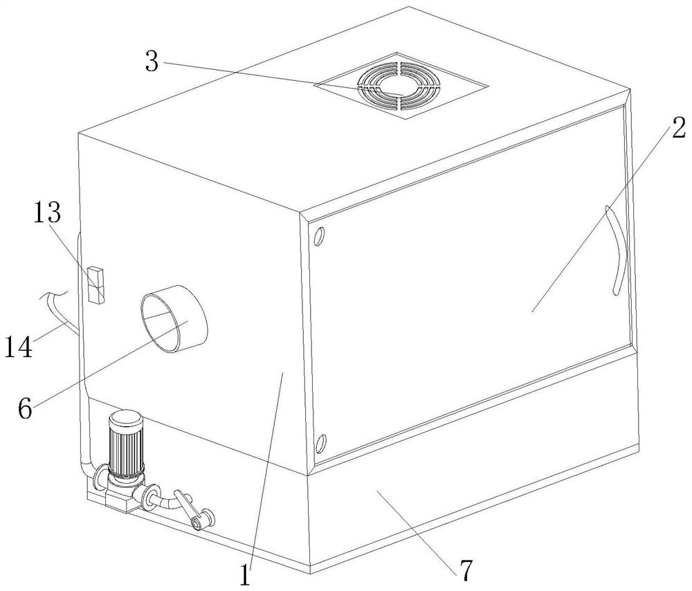
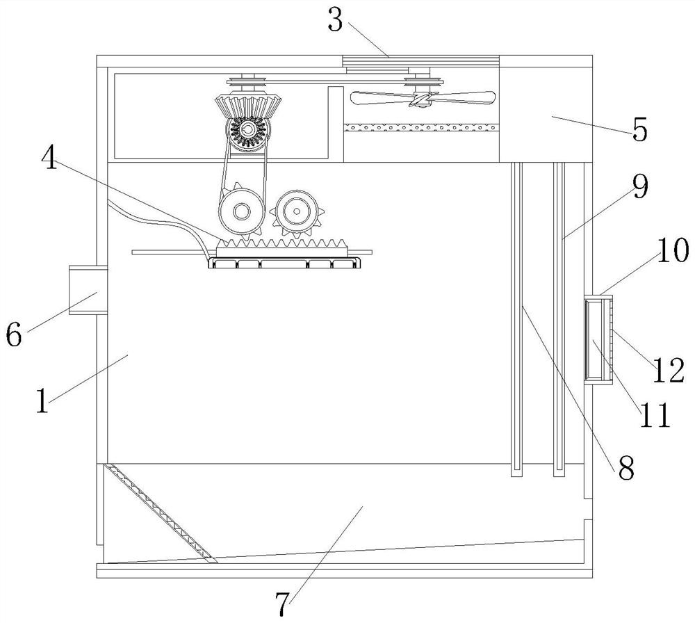
[0030] see figure 1 with figure 2 , a spray dust suppression structure for a mobile dust collector of the present invention, comprising a box body 1, an inspection door 2, a ventilation window 3, a processing mechanism 4, a mounting seat 5, an air intake cylinder 6, a water filter mechanism 7, a first filter screen 8, The second filter screen 9, the punching bag 10, the fan 11, the dustproof sheet 12, the control switch 13 and the power cord 14, the inspection door 2 is hinged at the front of the box body 1, the ventilation window 3 is embedded on the right side of the top of the box body 1, and the mounting seat 5 is embedded in the upper right corner of the box body 1, the air intake tube 6 is embedded in the middle of the left side of the box body 1 horizontally, the left and right sides of the bottom of the mounting seat 5 are respectively connected with the first filter screen 8 and the second filter screen 9, and the air outlet tube 10 is horizontally embedded in the O...

Embodiment 2

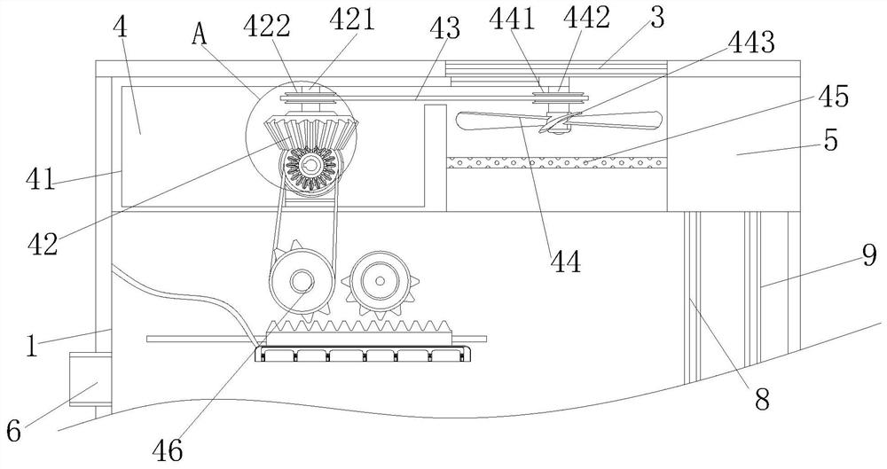
[0035] In the spray dust suppression structure for a mobile dust collector of the present invention, the large pulley 422 and the small pulley 442 are on the same horizontal plane, and the large pulley 422 and the small pulley 442 are connected by a transmission belt 43, while the large pulley 422 and the small pulley 442 The size ratio of the special-shaped gear 462 is 5:1, which is convenient for the small pulley 442 to accelerate the rotation. The ratio of the outer diameter of the rear side of the special-shaped gear 462 to the turntable 425 is 1:3, and the outer surface of the special-shaped gear 462 is connected with the turntable 425 through the transmission belt 461. It is beneficial to drive the special-shaped gear 462 to carry out deceleration movement. The angle formed by the bottom side of the rectangular groove seat 71 from left to right and the horizontal ground is 15 degrees, which is convenient for the flow of water. The top surface of the water outlet connecting...


PUM


Abstract

The invention discloses a spraying dust-falling structure for a mobile dust remover. The spraying dust-falling structure comprises a box body, an access door, a ventilation window, a treatment mechanism, a mounting seat, an air inlet cylinder, a water filtering mechanism, a first filter screen, a second filter screen, an air outlet cylinder, a fan, a dustproof sheet, a control switch and a power line. According to the invetion, by optimally arranging a treatment mechanism, when a driving motor rotates, fan blades are driven to rotate through a transmission belt while a rotating disc drives a special-shaped gear to rotate through the transmission belt, and a water collecting pipe reciprocates on a sliding rail under the cooperation of the special-shaped gear and a half gear, so that the fanblades rotate to drive an ion wind bar to generate ions to be blown into the box body, and under the reciprocating motion of water mist sprayed from the bottom of a water collecting pipe, the dust falling efficiency is improved; and by optimally arranging a water filtering mechanism, dust particles are filtered by obliquely-arranged filter screen sheets, and the filtered water is sucked by a water pump to be reused, so that the water is recycled, and the problem of water resource waste is avoided.

Description

technical field [0001] The invention relates to the related field of dust collectors, in particular to a spray dust suppression structure for a mobile dust collector. Background technique [0002] The mobile dust collector also has a good dust removal effect within a certain range for fine metal chips with a small specific gravity, foundry sand dust, cement, gypsum powder, charcoal powder, bakelite powder, plastic powder, etc., and the dust removal efficiency is greater than Ninety-nine point five percent; the mobile dust collector is usually equipped with a spray dust suppression structure to spray and suppress the sucked dust. [0003] The spray dust suppression structure of the prior art is relatively simple. Usually, the dust is sucked into the box by the fan through the suction pipe for processing. The dust is directly settled by combining with the water mist. When the amount of dust is large, the dust settlement efficiency is likely to be reduced, and It is not easy t...

Claims


Application Information

Patent Timeline
Patent Type & Authority Applications(China)
IPC IPC(8): B01D47/06B01D50/00
CPCB01D47/06B01D2247/02B01D2247/04B01D50/60
Inventor 邓春华
Owner 泉州市琼鑫工业设计有限公司
Why Eureka
Try Eureka