Universal deburring optical head device

A technology of bald head and mounting seat, which is applied in the direction of laser welding equipment, welding equipment, metal processing equipment, etc., can solve the problems of low processing accuracy and efficiency, low degree of integration, difficult to remove burrs, etc., and achieve the effect of improving quality and efficiency

Pending Publication Date: 2020-11-17
苏州麦尔科唯激光机器人有限公司
View PDF0 Cites 0 Cited by
  • Summary
  • Abstract
  • Description
  • Claims
  • Application Information

AI Technical Summary

Problems solved by technology

[0003] However, the current laser head assembly and optical path design process does not fully consider various factors. The output optical path of the deburring optical head is perpendicular to the processing surface. The operator needs to move the optical head by adjusting the coordinate system of the mechanical guide rail during the deburring process. The method is difficult to remove the burrs at the corners and edges of the workpiece, and the processing accuracy and efficiency are low, and there are processing dead ends; for the burrs at the corners and edges, the current technical solution is to first laser cut the overall burrs, and then use another weak ring laser The laser spot melts and removes the remaining burrs, which requires secondary or even multiple processing, which is cumbersome and wastes energy. At the same time, because the optical path is perpendicular to the processing surface, and the burrs on the surface in the feed direction are not located in the horizontal plane, it is difficult for the laser to scan. Causes burrs on corners and other fillets that are difficult to remove
[0004] In addition, the current deburring optical head generally adopts the mode of combining multiple focusing lenses for parallel light focusing, and the mode of external water cooler for cooling and maintenance. In the case of direct laser energy, the equipment cooling method is particularly important

Method used


Image

  • Universal deburring optical head device
  • Universal deburring optical head device
  • Universal deburring optical head device

Examples


Embodiment Construction

[0023] The technical solutions of the present invention will be further described below in conjunction with the accompanying drawings and specific embodiments.

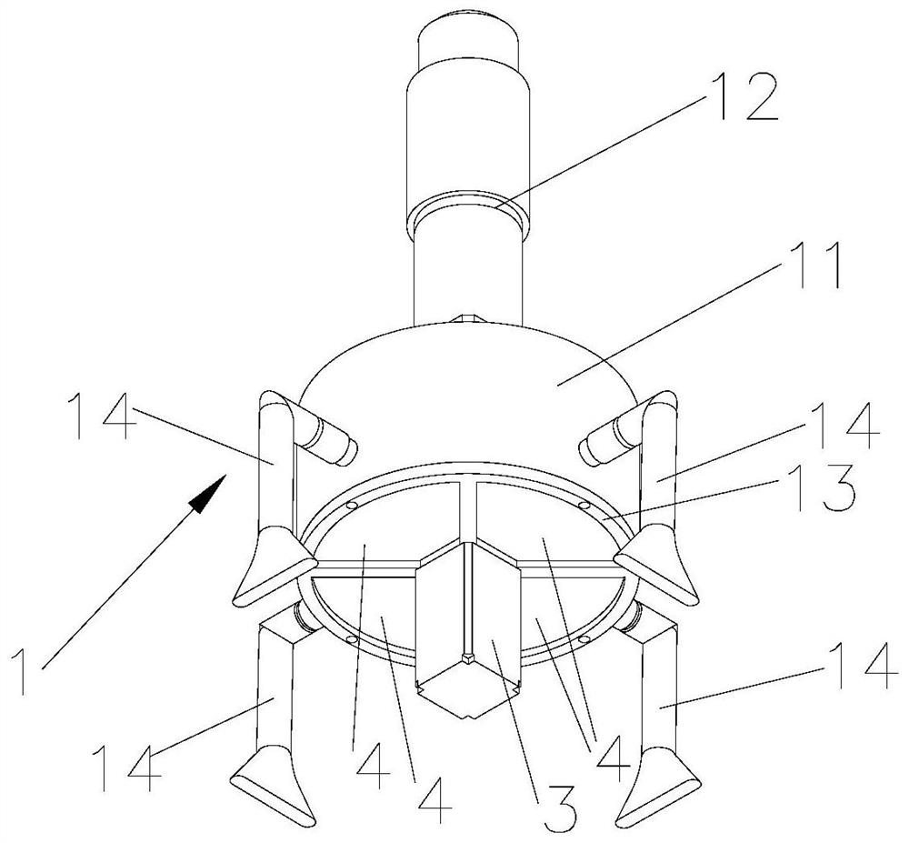
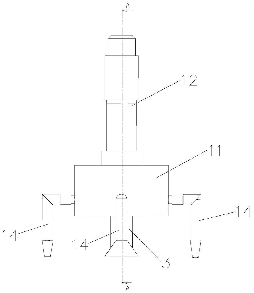
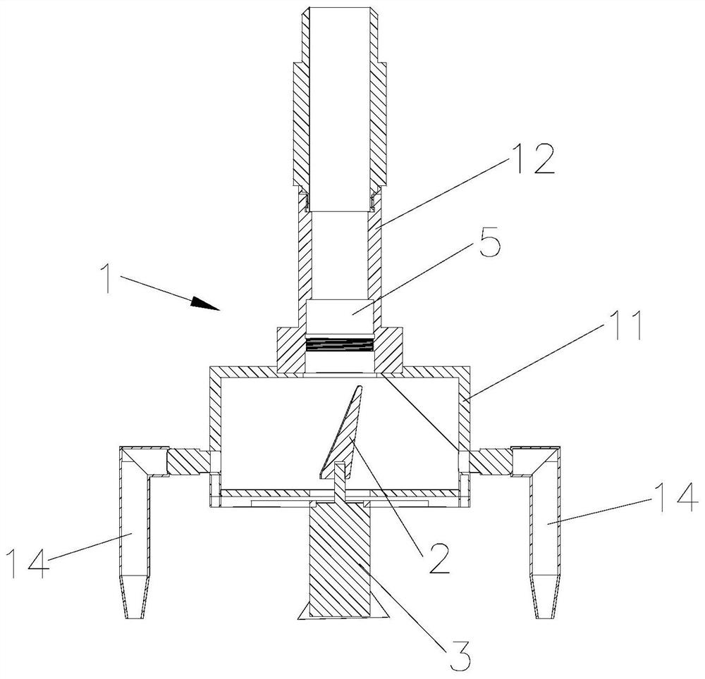
[0024] see Figure 1 to Figure 6 As shown, a kind of optical head device for universal deburring, the optical head device includes a bracket 1, a collimation system installed on the bracket 1, a parabolic mirror 2 that is rotatably connected to the bracket 1, and is used to drive the parabolic mirror 2 Rotary driving mechanism, wherein, the parabolic mirror 2 has a parabolic mirror surface 21, the parabolic mirror surface 21 is located on the light path of the collimation system, and the rotation center line of the parabolic mirror 2 is in line with the projection direction of the laser beam collimated by the collimation system parallel to each other.

[0025] Specifically, see image 3 , Figure 5 and Figure 6 As shown, the parabolic mirror 21 is slightly arched inward along the thickness direction of the parabo...


PUM


Abstract

The invention discloses a universal deburring optical head device. The optical head device comprises a support, a collimation system installed on the support, a paraboloidal mirror rotationally connected to the support and a driving mechanism used for driving the paraboloidal mirror to rotate, wherein the paraboloidal mirror is provided with a parabolic mirror surface, the parabolic mirror surfaceis located on a light emitting path of the collimation system, and the rotating center line of the parabolic mirror is parallel to the projection direction of a laser beam collimated by the collimation system. The paraboloidal mirror is driven to rotate, then the universal deburring function can be realized, meanwhile, the emitted laser beam is not perpendicular to the horizontal plane, therefore, burrs at corners and other rounded corners can be scanned, thus the laser deburring machining quality and efficiency are greatly improved, and in addition, the whole optical head device is made to be low in weight.

Description

technical field [0001] The invention relates to an optical head device for universal deburring. Background technique [0002] In the field of laser deburring, the latest technical solution is the combination of laser cutting burrs and melting burrs. Its principle is to convert a parallel laser beam into two energy gradient lasers through the laser head system, and then pass through different The lens with the focal length and the parabolic mirror focus to form concentric spot and ring spots on the processing surface. First use the high-energy-density point spot to cut the large burr, and then use the low-energy-density ring spot to melt the residual small burr. After testing, edge burrs can be removed. [0003] However, the current laser head assembly and optical path design process does not fully consider various factors. The output optical path of the deburring optical head is perpendicular to the processing surface. The operator needs to move the optical head by adjus...

Claims


Application Information

Patent Timeline
Patent Type & Authority Applications(China)
IPC IPC(8): B23K26/361
CPCB23K26/361
Inventor 刘卫兵王明娣蔡信健黄伟赵栋郭敏超王贤宝张晓倪玉吉
Owner 苏州麦尔科唯激光机器人有限公司
Why Eureka
Try Eureka