Cardboard printing equipment

A technology of printing equipment and cardboard, applied in printing, stamping, etc., can solve the problems of low work efficiency and poor effect, and achieve the effect of improving work efficiency and good effect

Inactive Publication Date: 2020-11-17
吴梅娇
View PDF12 Cites 21 Cited by
  • Summary
  • Abstract
  • Description
  • Claims
  • Application Information

AI Technical Summary

Problems solved by technology

[0004] In order to overcome the shortcomings of poor manual stamping and low work efficiency in the prior art, the technical problem of the present invention is to provide a cardboard printing device with good stamping effect and greatly improved work efficiency

Method used


Image

  • Cardboard printing equipment
  • Cardboard printing equipment
  • Cardboard printing equipment

Examples


Embodiment 1

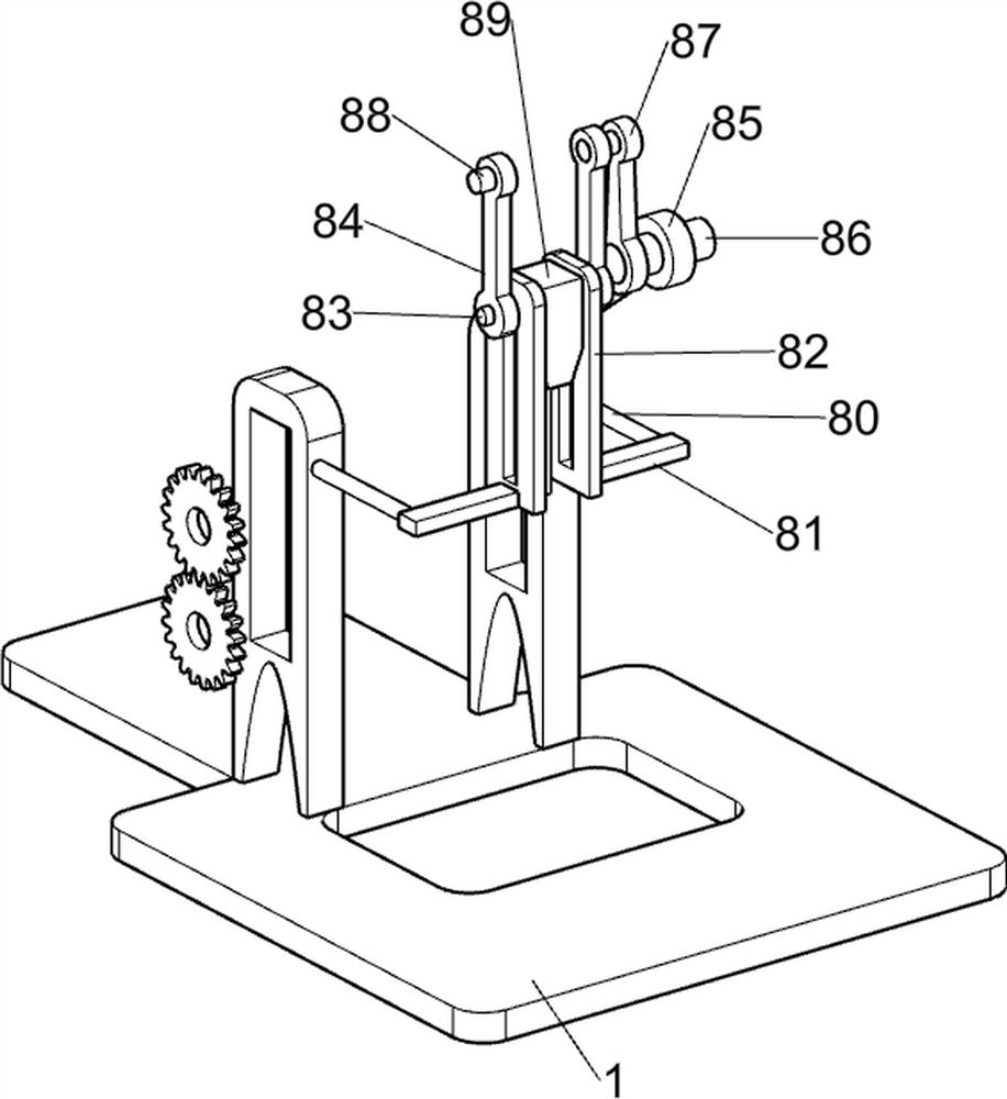
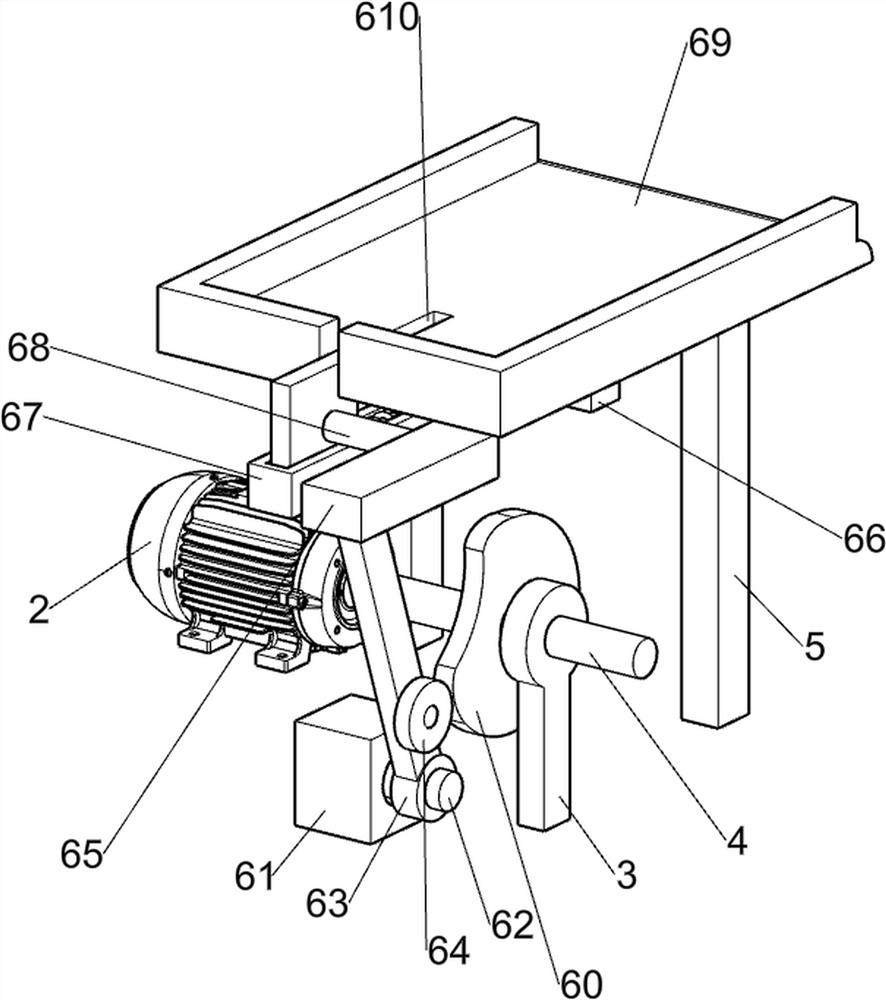
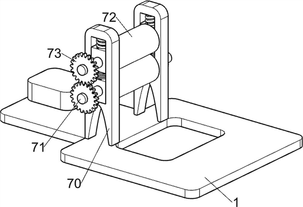
[0022] A cardboard printing device such as Figure 1-5 As shown, it includes a bottom plate 1, a servo motor 2, a first bearing seat 3, a first rotating shaft 4, a support rod 5, a pushing mechanism 6, a rotating mechanism 7, a stamp mechanism 8, a first transmission assembly 9, and a second transmission assembly 10. The third transmission assembly 12 and the fourth transmission assembly 13, the servo motor 2 is installed on the left side of the top of the bottom plate 1, the first bearing seat 3 is installed on the left front side of the top of the bottom plate 1, and the first bearing seat 3 is internally rotated. Revolving shaft 4, base plate 1 top left side front and rear symmetry are fixedly connected with support bar 5, are provided with pushing mechanism 6 between support bar 5 tops, are provided with rotating mechanism 7 and seal mechanism 8 in the middle of base plate 1 top, seal mechanism 8 and first The first transmission assembly 9 is connected between the rotating...

Embodiment 2

[0031] On the basis of Example 1, such as Figure 6-7 As shown, a blanking mechanism 11 is also included, and the blanking mechanism 11 includes a second support plate 110, a third support plate 111, a third bearing seat 112, a fourth rotating shaft 113, a fifth bearing seat 114, a first bevel gear 115, the fifth rotating shaft 116, the second bevel gear 117, the missing gear 118, the third slide rail 119, the second slider 1110, the first L-shaped bar 1111, the second spring 1112, the second L-shaped bar 1113, the fourth The slide rail 1114, the third slider 1115 and the opening and closing plate 1116, the top right side of the bottom plate 1 is fixedly connected with the second support plate 110 symmetrically front and back, the top right side of the bottom plate 1 is fixedly connected with two third support plates 111 and a third bearing Seat 112, the third bearing seat 112 is located between the third support plates 111, the third bearing seat 112 is provided with a fourth...


PUM


Abstract

The invention relates to printing equipment, in particular to cardboard printing equipment. The cardboard printing equipment provided is good in stamping effect and capable of greatly improving the working efficiency. The cardboard printing equipment comprises a bottom plate, a first bearing seat, and a first rotating shaft. A servo motor is installed on one side of the top of the bottom plate; the first bearing seat is mounted on the side, close to the servo motor, of the top of the bottom plate; and the first rotating shaft is arranged inside the first bearing seat in a rotating mode. According to the cardboard printing equipment, the effects that the stamping effect is good, and the working efficiency can be greatly improved are achieved. A crank is driven by a third rotating shaft to continuously rotate, so that a fifth connecting rod and a pressing block are driven to move downwards, so as to make a stamper move downwards to print a cardboard.

Description

technical field [0001] The invention relates to a printing device, in particular to a cardboard printing device. Background technique [0002] Cardboard is a thick paper sheet made of various pulps and interwoven fibers. It is generally divided into packaging cardboard, industrial technology cardboard and printing and decoration cardboard. In daily production and life, people often need to use cardboard Print some logos on it. [0003] At present, there are several ways to print marks on cardboard, such as printing with a roller printer or a flatbed printer, and printing directly on a cardboard with a stamp. When printing directly on a hardboard with a stamp , often people directly hold the seal and stamp on the cardboard one by one. This printing method has many disadvantages. It requires people to move the cardboard manually, which is very time-consuming and laborious, and the hands are constantly stamping, which may be due to strength. Insufficient, making the effect of...

Claims


Application Information

Patent Timeline
Patent Type & Authority Applications(China)
IPC IPC(8): B41K3/04B41K3/50B41K3/62
CPCB41K3/04B41K3/50B41K3/62
Inventor 吴梅娇
Owner 吴梅娇
Why Eureka
Try Eureka