Feeding and piece arranging device for electric injection furnace

A chip box and silicon wafer technology, applied in the directions of transportation and packaging, conveyor objects, etc., can solve the problems of cell collapse, edge defect, uneven cell, complicated structure, etc., and achieve the effect of improving the speed of chip removal.

Pending Publication Date: 2020-11-17
常州科瑞尔科技有限公司
View PDF0 Cites 0 Cited by
  • Summary
  • Abstract
  • Description
  • Claims
  • Application Information

AI Technical Summary

Problems solved by technology

One of the key control points of the electro-injection process is how to neatly stack the cells into a stack. The current feeding device on the market has the disadvantages of uneven stacking of the cells, which may easily lead to edge chipping and defect of the cells, and the equipment occupies an area of Large area and complicated structure

Method used


Image

  • Feeding and piece arranging device for electric injection furnace
  • Feeding and piece arranging device for electric injection furnace
  • Feeding and piece arranging device for electric injection furnace

Examples


Embodiment Construction

[0029] The specific embodiment of the present invention is further described below in conjunction with accompanying drawing:

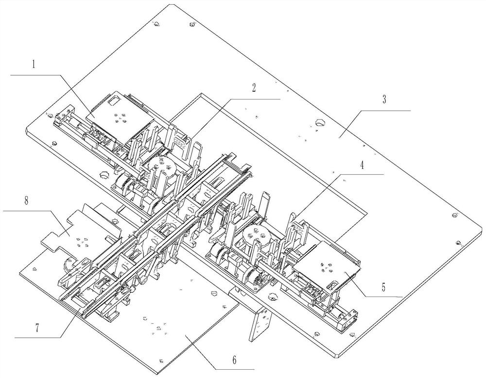
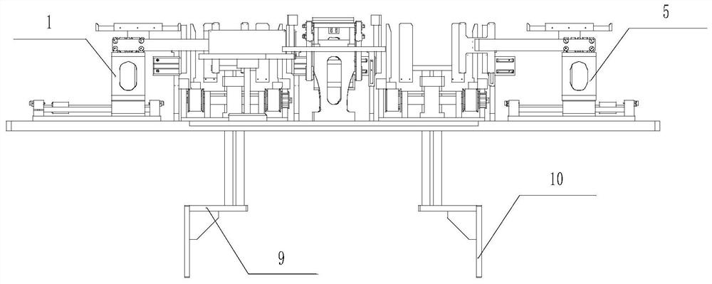
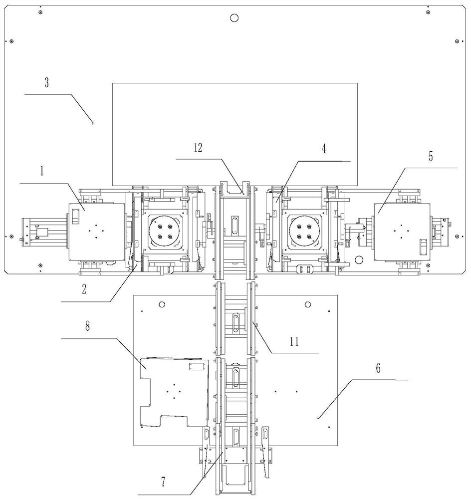
[0030] An electric injection furnace feeding device, characterized in that it includes a first front and rear straightening unit 1, a first left and right straightening unit 2, a fixing plate 3, a second left and right straightening unit 4, a second front and rear straightening unit 5, and a transmission rail Fixed plate 6, silicon wafer conveying line 7, temporary film cassette 8, first jacking rod 9, second jacking rod 10, middle conveying line body 11 and slice taking position conveying line 12, the first front and rear correction The unit 1 is installed on the top surface of the fixed plate 3, the first left and right correction unit 2 is fixedly installed on the top surface of the fixed plate 3 and the first left and right correction unit 2 is located on the right side of the first front and rear correction unit 1, and the first left and right corr...


PUM


Abstract

The invention discloses a feeding and piece arranging device for an electric injection furnace. The feeding and piece arranging device is characterized in that a first front-back correcting unit, a first left-right correcting unit, a piece taking position conveying line, a second left-right correcting unit and a second front-back correcting unit are sequentially and fixedly installed at the top face of a fixing plate from left to right, and a conveying rail fixing plate is located at the front side of the fixing plate; and a middle conveying line body is fixedly installed on the conveying railfixing plate and located at the front side of the piece taking position conveying line, a silicon wafer conveying line is fixedly installed on the conveying rail fixing plate and located at the frontside of the middle conveying line body, and a temporary storage piece box is installed on the conveying rail fixing plate and located at the left side of the silicon wafer conveying line. The feedingand piece arranging device is simple in structure and stable and reliable in work, the discharging speed is greatly increased, the situation that battery pieces are stacked due to the fact that the battery pieces cannot be conveyed in time is prevented, and extra damage to the battery pieces is avoided while the correction effect is guaranteed.

Description

technical field [0001] The invention belongs to the technical field of solar cell sheet processing equipment, and in particular relates to a charging device for an electric injection furnace. Background technique [0002] The electric injection method in the production of solar cells can significantly suppress the light attenuation benefit of monocrystalline silicon and polycrystalline silicon solar cells, and has the function of improving the conversion efficiency of solar cells and improving the actual power generation efficiency of the cells. Due to its technical characteristics, the electric injection furnace needs to stack the screen-printed and sintered cells, and add a conductive metal plate to the top and bottom of the stacked cells to passivate impurities and defects through current. One of the key control points of the electro-injection process is how to neatly stack the cells into a stack. The current feeding device on the market has the disadvantages of uneven st...

Claims


Application Information

Patent Timeline
Patent Type & Authority Applications(China)
IPC IPC(8): B65G47/74B65G47/91
CPCB65G47/74B65G47/91
Inventor 于彬李昂唐光明
Owner 常州科瑞尔科技有限公司
Why Eureka
Try Eureka