Stainless steel draught fan convenient to disassemble
A convenient disassembly, stainless steel technology, used in mechanical equipment, machines/engines, liquid fuel engines, etc., can solve the problems of difficult disassembly, inconvenient installation of stainless steel fans, hindering the normal installation of fans, etc., to ensure adaptability and easy installation and disassembly. Effect
- Summary
- Abstract
- Description
- Claims
- Application Information
AI Technical Summary
Problems solved by technology
Method used
Image
Examples
Embodiment 1
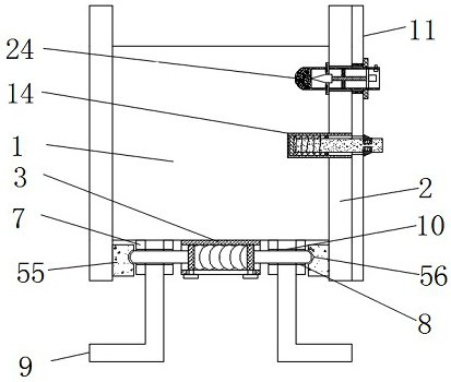
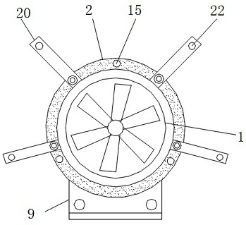
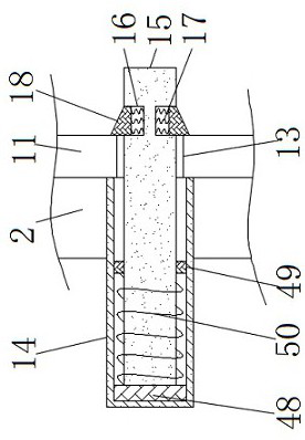
[0038] see Figure 1-10 According to an embodiment of the present invention, a stainless steel fan that is convenient to disassemble includes a stainless steel fan body 1, connecting rings 2 are fixedly connected to both sides of the stainless steel fan body 1, and a connecting sleeve is fixedly connected to the bottom of the stainless steel fan body 1 3. The inside of the connection sleeve 3 is connected to the movable block 5 through the spring 4, and the movable block 5 is attached to the inner wall of the connection sleeve 3, and the side of the movable block 5 away from the spring 4 is fixedly connected There is a connecting rod-6, a silicone pad 55 is fixedly connected to the inner side of the connecting ring 2 and close to the connecting rod-6, and the side of the silicone pad 55 close to the connecting rod-6 has an arc groove 56, The silica gel pad 55 and the curved surface groove 56 serve to limit the position of the connecting rod-6 port, and the two sides of the con...
Embodiment 2
[0043] see Figure 9 , the push block 28 includes a gentle portion 33, a conical surface 34 and an arc surface 35, the bottom of the gentle portion 33 is provided with a conical surface 34, and the cooperation between the gentle portion 33 and the conical surface 34 can realize the promotion of the connecting block 2 27 , the bottom of the conical surface 34 is provided with an arc surface 35 , and the arc surface 35 can fit better with the inner wall of the cavity 25 .
Embodiment 3
[0045] see Figure 7-8 , the limiting mechanism includes a through hole 2 36, a limiting block 2 37 and a connecting block 3 38, the port of the cavity 25 is provided with a through hole 2 36, and one end of the limiting block 2 37 runs through the through hole Two 36 and located outside the connecting rod three 24, the other end of the limiting block two 37 is located in the cavity 25 and connected with the connecting block three 38, the inside of the cavity 25 is close to the connecting block three 38 places are equipped with extrusion mechanism;
[0046] The extrusion mechanism includes a fixed sleeve 39, a spring three 40, an extrusion plate 41, a through hole three 42, a moving rod 43 and a connection block four 44, and the inner wall of the cavity 25 is fixed on the periphery of the connection block three 38. A fixed sleeve 39 is connected, and the inside of the fixed sleeve 39 is connected to the extruding plate 41 through the spring three 40, the extruding plate 41 is...
PUM
 Abstract
Description
Claims
Application Information
 - R&D
- Intellectual Property
- Life Sciences
- Materials
- Tech Scout
- Unparalleled Data Quality
- Higher Quality Content
- 60% Fewer Hallucinations
Browse by: Latest US Patents, China's latest patents, Technical Efficacy Thesaurus, Application Domain, Technology Topic, Popular Technical Reports.
© 2025 PatSnap. All rights reserved.Legal|Privacy policy|Modern Slavery Act Transparency Statement|Sitemap|About US| Contact US: help@patsnap.com


