
A stainless steel fan that is easy to disassemble

A convenient disassembly, stainless steel technology, used in mechanical equipment, machines/engines, liquid fuel engines, etc., can solve the problems of difficult disassembly, inconvenient installation of stainless steel fans, hindering the normal installation of fans, etc., to ensure adaptability and easy installation and disassembly. Effect

Active Publication Date: 2021-06-29
JIANGSU HENGKANG ELECTRICAL
View PDF7 Cites 0 Cited by
  • Summary
  • Abstract
  • Description
  • Claims
  • Application Information

AI Technical Summary

Problems solved by technology

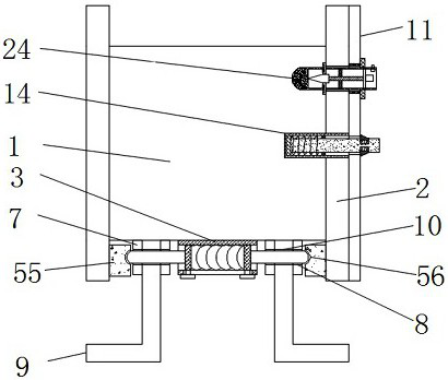
[0003] The fan is made of stainless steel, which can reduce the corrosion of the gas to the fan as a whole, thereby prolonging the service life of the fan. However, the existing installation environment is varied, and the stainless steel fan is required to adapt to different installation environments, so different auxiliary installation parts are required. It is installed, but if all the auxiliary parts are installed on the stainless steel fan, it will cause inconvenience in the installation of the stainless steel fan and hinder the normal installation of the fan. Therefore, it is necessary to use different auxiliary installation parts according to different environments. The existing auxiliary parts It is connected and fixed with the stainless steel fan by welding, and there is a problem of difficulty in disassembly, and once one of the auxiliary parts is installed on the stainless steel fan, the installation environment of the stainless steel fan is limited, so that the stainless steel fan cannot adapt to other environments, resulting in Due to the limitations of stainless steel fans, there is a need for a stainless steel fan that can easily disassemble auxiliary installation parts

Method used


Image

  • A stainless steel fan that is easy to disassemble
  • A stainless steel fan that is easy to disassemble
  • A stainless steel fan that is easy to disassemble

Examples


Embodiment 1

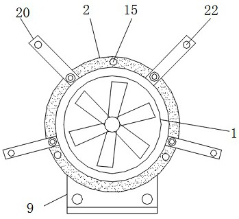
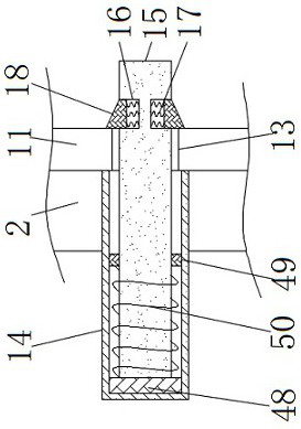
[0038] see Figure 1-10 According to an embodiment of the present invention, a stainless steel fan that is convenient to disassemble includes a stainless steel fan body 1, connecting rings 2 are fixedly connected to both sides of the stainless steel fan body 1, and a connecting sleeve is fixedly connected to the bottom of the stainless steel fan body 1 3. The inside of the connection sleeve 3 is connected to the movable block 5 through the spring 4, and the movable block 5 is attached to the inner wall of the connection sleeve 3, and the side of the movable block 5 away from the spring 4 is fixedly connected There is a connecting rod-6, a silicone pad 55 is fixedly connected to the inner side of the connecting ring 2 and close to the connecting rod-6, and the side of the silicone pad 55 close to the connecting rod-6 has an arc groove 56, The silica gel pad 55 and the curved surface groove 56 serve to limit the position of the connecting rod-6 port, and the two sides of the con...

Embodiment 2

[0043] see Figure 9 , the push block 28 includes a gentle portion 33, a conical surface 34 and an arc surface 35, the bottom of the gentle portion 33 is provided with a conical surface 34, and the cooperation between the gentle portion 33 and the conical surface 34 can realize the promotion of the connecting block 2 27 , the bottom of the conical surface 34 is provided with an arc surface 35 , and the arc surface 35 can fit better with the inner wall of the cavity 25 .

Embodiment 3

[0045] see Figure 7-8 , the limiting mechanism includes a through hole 2 36, a limiting block 2 37 and a connecting block 3 38, the port of the cavity 25 is provided with a through hole 2 36, and one end of the limiting block 2 37 runs through the through hole Two 36 and located outside the connecting rod three 24, the other end of the limiting block two 37 is located in the cavity 25 and connected with the connecting block three 38, the inside of the cavity 25 is close to the connecting block three 38 places are equipped with extrusion mechanism;

[0046] The extrusion mechanism includes a fixed sleeve 39, a spring three 40, an extrusion plate 41, a through hole three 42, a moving rod 43 and a connection block four 44, and the inner wall of the cavity 25 is fixed on the periphery of the connection block three 38. A fixed sleeve 39 is connected, and the inside of the fixed sleeve 39 is connected to the extruding plate 41 through the spring three 40, the extruding plate 41 is...


PUM


Abstract

The invention discloses an easily disassembled stainless steel fan, comprising a stainless steel fan body, two sides of the stainless steel fan body are fixedly connected with connecting rings, the bottom of the stainless steel fan body is fixedly connected with a connecting sleeve, and the interior of the connecting sleeve is The first spring is connected to the movable block, the movable block is fixedly connected with a connecting rod, and both sides of the connecting sleeve are provided with a connecting block. A support plate is arranged between the first connection block, and the top of the support plate is provided with a second connection hole matching the first connection hole, and the first connection rod passes through the first connection hole and the second connection hole, so The air inlet end of the stainless steel fan body is provided with a circular ring, the interior of the circular ring is fixedly connected with a protective net, the side of the circular ring away from the center of the circle is opened with an opening, and a mounting plate is arranged in the opening. Beneficial effects: the fan is connected with the stainless steel fan in a detachable manner, and the installation and removal operations are simple.

Description

technical field [0001] The invention relates to the technical field of fans, in particular to a stainless steel fan which can be easily disassembled. Background technique [0002] The fan is a machine that relies on the input mechanical energy to increase the gas pressure and discharge the gas. It is a driven fluid machine. Fans are mainly used in metallurgy, petrochemical, electric power, urban rail transit, textile, shipbuilding and other fields of national economy and ventilation in various places. In addition to traditional application fields, there will still be great development prospects in more than 20 potential market fields such as comprehensive utilization of coal gangue, technical transformation of new dry process clinker, energy saving in metallurgical industry, and comprehensive utilization of resources. [0003] The fan is made of stainless steel, which can reduce the corrosion of the gas to the fan as a whole, thereby prolonging the service life of the fan. ...

Claims


Application Information

Patent Timeline
Patent Type & Authority Patents(China)
IPC IPC(8): F04D25/08F04D29/02F04D29/64
CPCF04D25/08F04D29/023F04D29/646
Inventor 刘万勤董传友刘正东刘迪群张为军孙勇安
Owner JIANGSU HENGKANG ELECTRICAL
Learn More