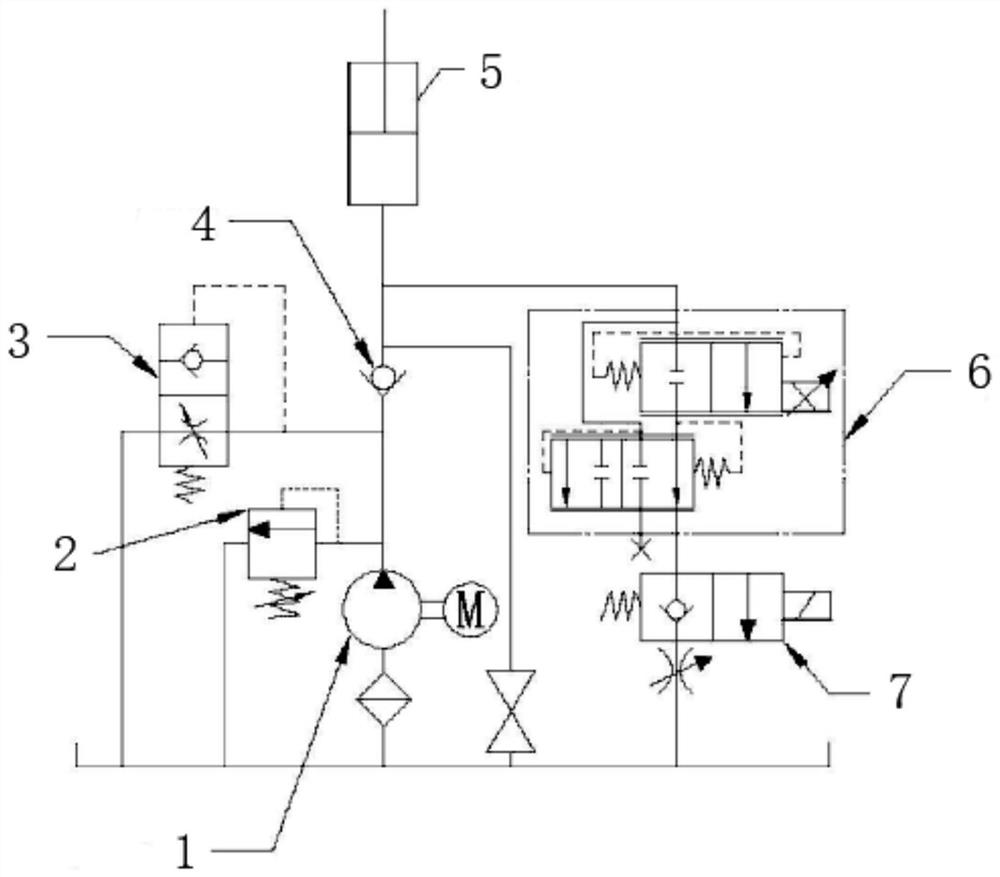
Power unit with proportional flow control valve and cartridge flow cushion valve

A flow control valve and power unit technology, applied in fluid pressure actuating devices, fluid pressure actuating system components, servo motors, etc., can solve the problems of unsolvable vibration and low equipment operation efficiency, and achieve elimination of vibration and improved operation. The effect of efficiency

Pending Publication Date: 2020-11-17
济南济力机械设备有限公司
View PDF0 Cites 0 Cited by
  • Summary
  • Abstract
  • Description
  • Claims
  • Application Information

AI Technical Summary

Problems solved by technology

[0005] The object of the present invention is to provide a power unit with a proportional flow control valve and a plug-in flow buffer valve. Vibration when extending and retracting, which improves th

Method used


Image

  • Power unit with proportional flow control valve and cartridge flow cushion valve

Examples


Embodiment Construction

[0014] The following will clearly and completely describe the technical solutions in the embodiments of the present invention with reference to the accompanying drawings in the embodiments of the present invention. Obviously, the described embodiments are only some, not all, embodiments of the present invention. Based on the embodiments of the present invention, all other embodiments obtained by persons of ordinary skill in the art without making creative efforts belong to the protection scope of the present invention.

[0015] In the description of the present invention, it should be noted that the terms "upper", "lower", "inner", "outer", "front end", "rear end", "both ends", "one end", "another end" The orientation or positional relationship indicated by etc. is based on the orientation or positional relationship shown in the drawings, and is only for the convenience of describing the present invention and simplifying the description, rather than indicating or implying that ...


PUM


Abstract

The invention discloses a power unit with a proportional flow control valve and a cartridge flow cushion valve. The power unit comprises a vane pump and an oil cylinder, wherein an oil outlet port ofthe vane pump communicates with an oil inlet port of the oil cylinder through a first pipeline, an overflow valve, the cartridge flow cushion valve and a one-way valve are sequentially fixed to the first pipeline between the oil outlet port of the vane pump and the oil inlet port of the oil cylinder, an oil outlet port of the oil cylinder communicates with an oil tank communicating with the vane pump through a second pipeline, and the proportional flow control valve and a two-position two-way normally-closed electromagnetic valve are sequentially fixed to the second pipeline between the oil outlet port of the oil cylinder and the oil tank communicating with the vane pump. The power unit has the advantages that the proportional flow control valve and the cartridge flow cushion valve are additionally arranged in the power unit to eliminate vibration generated when the oil cylinder controlled by the power unit stretches out and draws back, and the operation efficiency is improved.

Description

technical field [0001] The invention relates to the technical field of power units, in particular to a power unit with a proportional flow control valve and a plug-in flow buffer valve. Background technique [0002] The power unit is a hydraulic power device with a control function. The hydraulic power unit is used as an oil supply device. It is connected to several hydraulic cylinders through an external pipeline system to control multiple sets of valve actions. Mainly, the extension of the oil cylinder is controlled by the motor-driven oil pump; the retraction of the oil cylinder is controlled by the solenoid valve. [0003] The existing power unit cannot control the acceleration and deceleration when the oil cylinder extends and retracts, and the vibration is too large when starting and stopping. [0004] Existing products cannot solve the problem of vibration, and can only reduce the operating speed to minimize vibration. Cause the equipment operation efficiency to be ...

Claims


Application Information

Patent Timeline
IPC IPC(8): F15B11/08F15B13/02F15B21/08
CPCF15B11/08F15B13/02F15B13/027F15B21/08
Inventor 王颖涛
Owner 济南济力机械设备有限公司
Why Eureka
Try Eureka