Modular combined assembly type anti-seismic support hanger
A combined assembly, support and hanger technology, applied in the direction of pipeline supports, electrical components, pipes/pipe joints/pipe fittings, etc., can solve problems affecting the appearance, affecting the use of pipelines, and intertwined pipelines, etc., to reduce vibration and impact , prevent the effect of affecting the use, flexible combination and assembly
- Summary
- Abstract
- Description
- Claims
- Application Information
AI Technical Summary
Problems solved by technology
Method used
Image

Examples
Embodiment 1
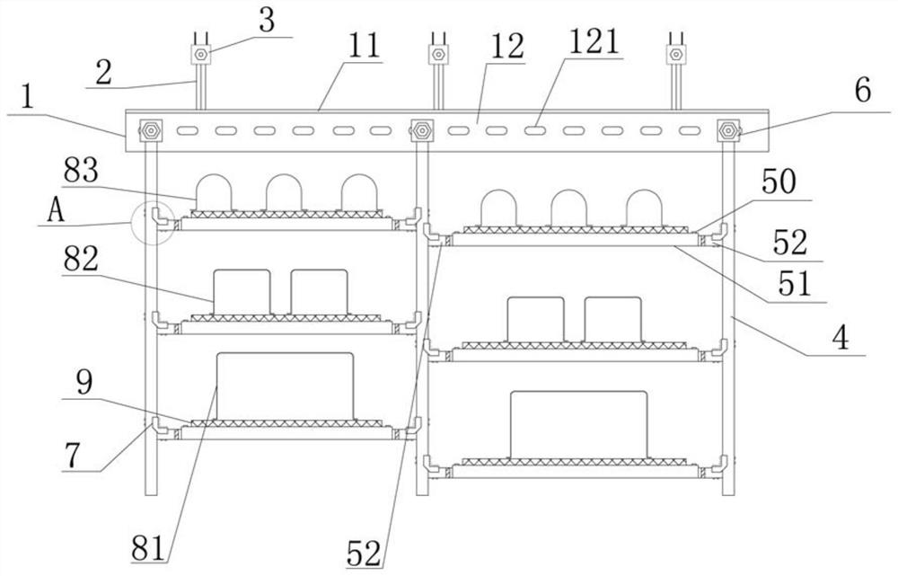
[0036] Embodiment one: if Figure 1-Figure 8As shown, a modularized assembled anti-seismic support and hanger of the present invention includes a row of support and hangers, and the support and hanger includes a T-shaped beam 1, at least two of which are fixedly connected to the upper part of the T-shaped beam 1 and extend parallel upwards. Long connecting rods 2, at least two vertical suspension rods 4 that are firmly connected to the lower part of the T-beam 1 and extend parallel downwards, and at least one telescopic bar 5. The length of the T-beam 1 is approximately equal to the width of the corridor. The T-shaped beam 1 comprises a beam plate 11 and a vertical beam plate 12 which are integrally provided. A plurality of adjustment holes 121 are equidistantly provided on the vertical beam plate 12. The adjustment holes 121 are selected as waist-shaped holes or circular holes. The length of the T-shaped beam 1 is approximately equal to the width of the corridor, and it plays...
Embodiment 2
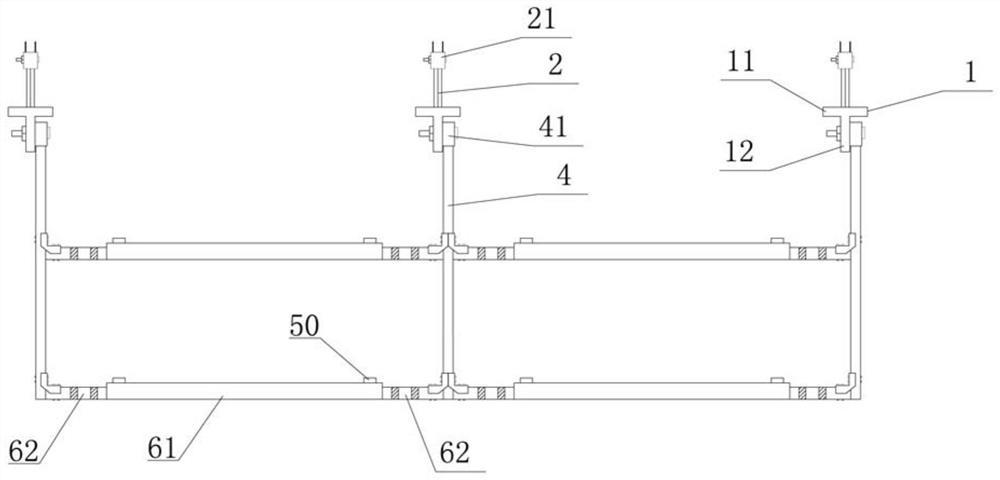
[0038] Embodiment 2: On the basis of Embodiment 1, the present invention includes two rows of support hangers, respectively the first support hanger and the second support hanger, the first support hanger and the second support hanger along the pipe length The direction is horizontal and parallel. The two sides of the first hanger and the second hanger are respectively connected by at least one side telescopic cross bar 6. The side telescopic cross bar 6 includes a side middle cross bar made of U-shaped channel steel. The rod 61 and the two side-end cross-bars 62 respectively movably embedded in the two ends of the side-middle cross-bar 61, the side-end cross-bar 62 and the side-middle cross-bar 61 are equidistantly provided with a plurality of second positioning holes 621, 611 respectively, The side cross bar 62 and the side middle cross bar 61 cooperate with the second positioning holes 621, 611 through the bolt 50 and the nut to adjust the length of the side end cross bar 62...
Embodiment 3
[0040] Embodiment three: on the basis of embodiment one, as figure 1 , figure 2 As shown, the present invention includes three rows of hangers, respectively the first hanger, the second hanger and the third hanger, the first hanger, the second hanger and the third hanger along the The length direction of the pipe fittings is transverse and parallel set up, The two sides of the first hanger, the second hanger and the third hanger are respectively connected by at least two side telescopic cross bars 6 . The preferred scheme of this embodiment is that the two sides between the first hanger and the second hanger are respectively connected by two upper and lower side telescopic cross bars 6, and the two sides between the second hanger and the third hanger The sides are respectively connected by two upper and lower side telescopic cross bars 6 . The side telescopic crossbar 6 includes a side middle crossbar 61 made of U-shaped channel steel and two side end crossbars 62 respec...
PUM
 Abstract
Description
Claims
Application Information
 - Generate Ideas
- Intellectual Property
- Life Sciences
- Materials
- Tech Scout
- Unparalleled Data Quality
- Higher Quality Content
- 60% Fewer Hallucinations
Browse by: Latest US Patents, China's latest patents, Technical Efficacy Thesaurus, Application Domain, Technology Topic, Popular Technical Reports.
© 2025 PatSnap. All rights reserved.Legal|Privacy policy|Modern Slavery Act Transparency Statement|Sitemap|About US| Contact US: help@patsnap.com