
Target body automatic identification method based on laser scanning

An automatic identification and laser scanning technology, applied in the field of measurement, can solve problems such as incapable of high-precision positioning services, inability to accurately identify measurement targets, and complex overall structure of the device, achieving simple structure, wide application range, and improved angle recognition accuracy Effect

Pending Publication Date: 2020-11-17
四川道通达工程技术有限公司 +1
View PDF1 Cites 1 Cited by
  • Summary
  • Abstract
  • Description
  • Claims
  • Application Information

AI Technical Summary

Problems solved by technology

[0004] 1. The laser emitting device is located in the scanning device, the laser receiving device is placed at the position of the target object, and each device needs power supply, resulting in the overall structure of the device being too complicated
[0005] 2. When scanning and positioning, only one laser rotating scanning device is supported to scan the monitoring area at the same time, and the operation efficiency is low
[0006] 3. The one-character laser module, photoelectric switch and rotation angle used in the whole set of equipment are based on two assumptions that the rotational angular velocity is constant, which indicates that the measurement accuracy of the whole set of equipment is low, and its actual measurement accuracy will basically not exceed 1′ , so it is not capable of high-precision positioning services with an accuracy of not less than 1″
[0007] 4. When there are multiple measurement targets, it is difficult to accurately identify the measurement targets

Method used


Image

  • Target body automatic identification method based on laser scanning
  • Target body automatic identification method based on laser scanning
  • Target body automatic identification method based on laser scanning

Examples


Embodiment 1

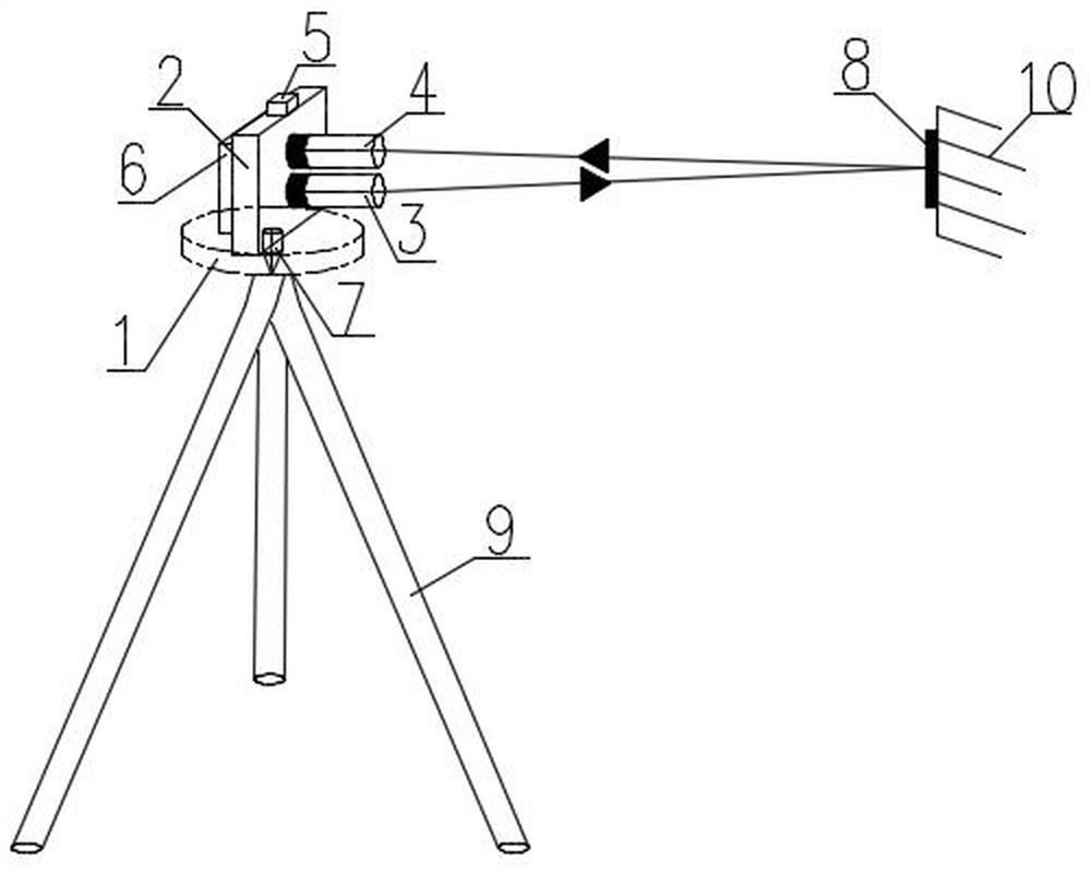
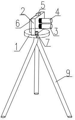
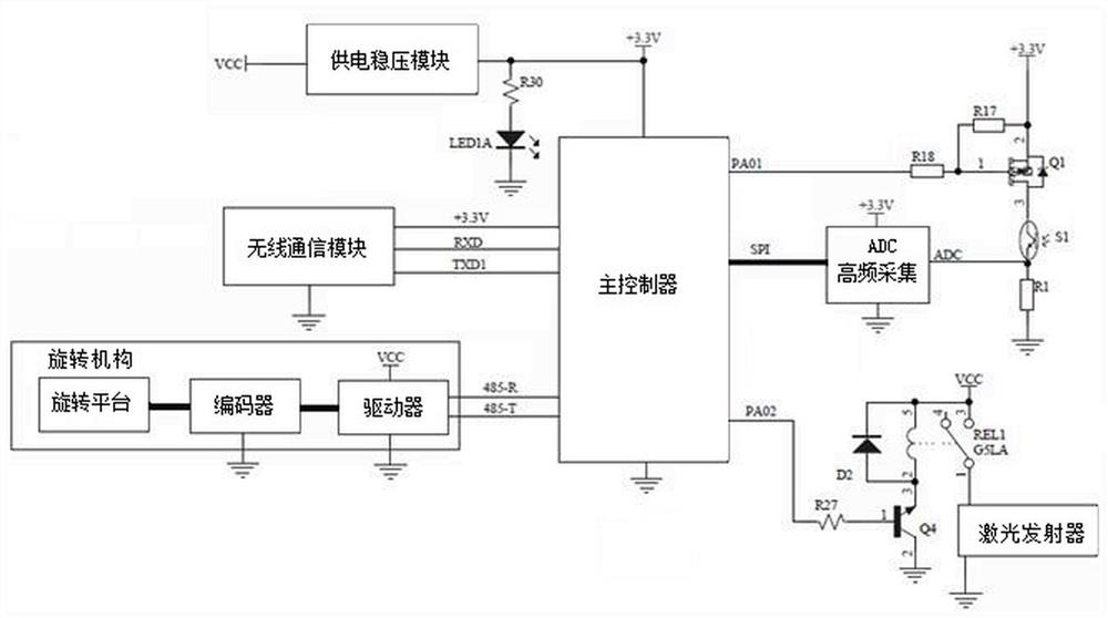
[0042] The invention discloses a method for automatic recognition of objects based on laser scanning, such as figure 1 shown, including the following steps:

[0043] Step 1: Set up a rotating laser transceiver at a designated location, and set a laser-reflecting target 10 in any area that the rotary laser transceiver can scan. The target 10 has a unique code.

[0044] Wherein, the number of target objects 10 is at least one, and when the number of target objects 10 exceeds one, multiple target objects 10 can be recognized simultaneously. The target body 10 is made of light-reflecting material 8, which can reflect the laser signal in the same way. The unique code of the target 10 is a barcode or electronic label placed on the reflective material 8 , and when the target 10 is scanned, the identity of the target 10 can be identified by analyzing the unique code.

[0045] Step 2: Control the rotating laser transceiver device to continuously rotate and continuously emit laser sig...

Embodiment 2

[0063] This embodiment has verified the technical solution described in embodiment 1, as follows:

[0064] 1. Equipment selection

[0065]

[0066] 2. Test content

[0067] Select a fixed point on the site to set up the rotating laser transceiver device, and set up two target objects within the visible range of the rotary laser transceiver device. Reflective materials with unique codes are arranged on the target objects, and the distance between the fixed points is two The horizontal distances of the two targets are 38 meters and 70 meters respectively.

[0068] 3. Test process

[0069] (1) Set up the rotating platform on the fixed point through the centering of the measuring tripod, and then start the equipment to rotate continuously at low speed for 10 circles.

[0070] (2) Control the rotating laser transceiver device to continuously rotate and continuously emit laser signals, and at the same time continuously collect the rotation angle and the laser signals reflected...


PUM


Abstract

The invention discloses a target body automatic identification method based on laser scanning, and the method comprises the following steps: 1, erecting a rotary laser receiving and transmitting device, setting a target body capable of reflecting laser in a scanning region, and enabling the target body to have a unique code; 2, controlling the rotary laser transceiving device to continuously rotate and continuously transmit laser signals, and continuously acquiring a rotation angle and the laser signals reflected by the target body at high frequency at the same time; and step 3, analyzing andprocessing the rotation angle and the laser signal reflected by the target body, identifying the identity of the target body, extracting a central angle value of the target body relative to a rotary platform in the rotary laser transceiving device, and then obtaining the relative position of the target body and the rotary laser transceiving device in the scanning area according to the central angle value. The method depends on unique coding, transmitting and receiving integration and same-direction rotation, does not need technical processing such as positioning, high-frequency acquisition andmulti-time superposition, and achieves accurate and automatic identification of the target body.

Description

technical field [0001] The invention relates to the field of measurement technology, in particular to an automatic target recognition method based on laser scanning, which is mainly used in industries requiring target recognition and positioning. Background technique [0002] In the field of engineering surveying, the identification of conventional surveying targets is mainly done through the manual sighting of surveyors. The measurement robot ensures that the target appears in the field of view of the lens by inputting the precise position of the object to be measured in advance, and then completes the specific mark (prism lens) in a fixed position in the field of view of the lens through a motor to achieve target recognition. All of these require the technical services of professional surveyors. How to lower the technical threshold of the surveying industry is a technical problem in the current surveying industry. [0003] Due to the characteristics of monochromaticity an...

Claims


Application Information

Patent Timeline
IPC IPC(8): G01S17/06G01S17/88G01S7/481
CPCG01S17/06G01S17/88G01S7/4817
Inventor 李跃伟何清友黄珂王俊潘启云余科唐勇
Owner 四川道通达工程技术有限公司
Learn More