New energy automobile motor heat dissipation frame
A heat dissipation technology for new energy vehicles and motors, which is applied in the direction of electrical components, electromechanical devices, electric components, etc. It can solve problems affecting the heat dissipation performance of heat sinks and the normal operation of motors, and achieve improved heat dissipation effects, improved heat dissipation performance, and improved heat dissipation effect of ability
- Summary
- Abstract
- Description
- Claims
- Application Information
AI Technical Summary
Problems solved by technology
Method used
Image

Examples
Embodiment 1
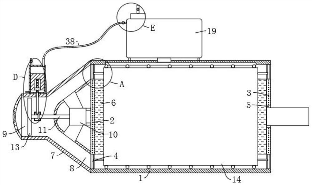
[0033] refer to Figure 1-8, a new energy vehicle motor cooling frame, including a cylinder 1, the two ends of the cylinder 1 are fixedly connected with a left partition 2 and a right partition 3 through a plurality of circumferentially distributed struts 4, the left partition 2, the right partition An annular groove 12 is arranged between the partition 3 and the inner wall of the cylinder 1, and an automobile motor 6 is fixedly installed between the left partition 2 and the right partition 3. The through hole 5 fitted with the shaft, the left side wall of the left partition 2 is fixedly equipped with a cooling motor 10, the left side of the cooling motor 10 is provided with a casing 7 fixedly connected with the left partition 2 and the side wall of the cylinder 1, the casing The inside of 7 is provided with a cavity 8 communicating with the annular groove 12, and the left end of the casing 7 is provided with a suction port 9 communicating with the cavity 8, and the output end...
Embodiment 2
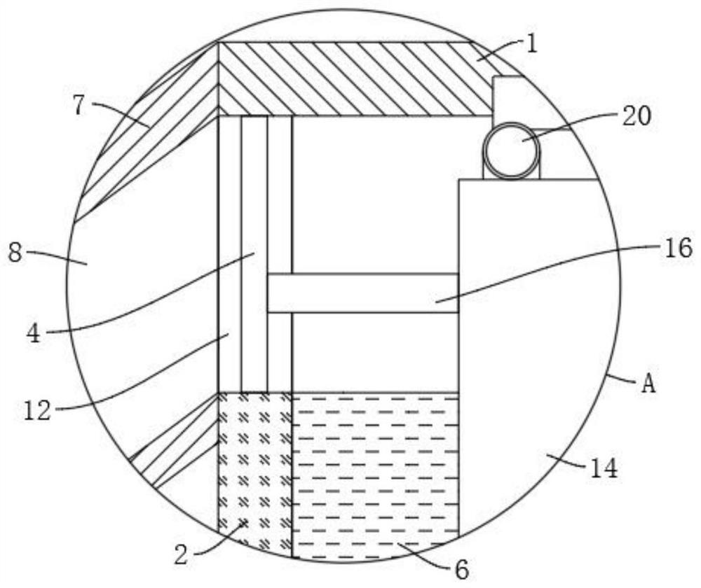
[0039] refer to image 3 , Figure 4 and Figure 8 , is basically the same as Embodiment 1, furthermore: the automatic dust removal device includes a rotating rod 16 arranged in the heat dissipation hole 15, and the rotating rod 16 is rotatably connected between two symmetrically arranged poles 4, and the rotating rod 16 The outer wall is fixedly connected with two symmetrically arranged cleaning plates 18, and the ends of the two cleaning plates 18 are all provided with cleaning brushes 42 fitted to the inner walls of the cooling holes 15, and the left end of the rotating rod 16 is fixedly equipped with a driving fan blade 17. The left end of bar 16 is fixedly installed with driving fan blade 17, and driving fan blade 17 can drive rotating rod 16 to rotate under the effect of blowing, and rotating rod 16 can drive cleaning plate 18 to rotate, and cleaning plate 18 can drive cleaning brush 42 pairs. The inner wall of the heat dissipation hole 15 is brushed to loosen the dust...
Embodiment 3
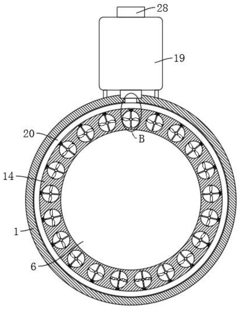
[0041] refer to figure 1 , figure 2 , Figure 4 and Figure 5 , is basically the same as Embodiment 1, furthermore: the enhanced heat dissipation device includes a plurality of heat dissipation pipes 20 fixedly connected to the outer wall of the heat dissipation cylinder 14, and the plurality of heat dissipation pipes 20 are evenly distributed on the outer wall of the heat dissipation cylinder 14, and the lower end of the water tank 19 A water outlet pipe 21 is provided, and a plurality of heat dissipation pipes 20 are fixedly connected and communicated through a connecting pipe 22. The lower ends of the water outlet pipes 21 are fixedly connected and communicated with the connecting pipe 22, and the inner walls of the plurality of heat dissipation pipes 20 are provided with a plurality of cooling holes. 15 connected tapered mouth 23, a plurality of tapered mouths 23 outlets are provided with tapered stop 24, the tapered mouth 23 is fixedly connected to the hollow bracket 2...
PUM
 Abstract
Description
Claims
Application Information
 - Generate Ideas
- Intellectual Property
- Life Sciences
- Materials
- Tech Scout
- Unparalleled Data Quality
- Higher Quality Content
- 60% Fewer Hallucinations
Browse by: Latest US Patents, China's latest patents, Technical Efficacy Thesaurus, Application Domain, Technology Topic, Popular Technical Reports.
© 2025 PatSnap. All rights reserved.Legal|Privacy policy|Modern Slavery Act Transparency Statement|Sitemap|About US| Contact US: help@patsnap.com