Automatic feeding and positioning equipment for motor rotor

A technology for positioning equipment and motor rotors, applied in metal processing equipment, manufacturing stator/rotor bodies, conveyors, etc., can solve problems such as low work efficiency, reduced installation accuracy, and easy to produce deviations, so as to increase the assembly effect and reduce the Manpower consumption, reduce the effect of wrong loading

Pending Publication Date: 2020-11-17
赣州中科拓又达智能装备科技有限公司
View PDF0 Cites 0 Cited by
  • Summary
  • Abstract
  • Description
  • Claims
  • Application Information

AI Technical Summary

Problems solved by technology

[0004] The purpose of the present invention is to provide an automatic feeding and positioning equipment for motor rotors to solve the problem that the existing tiny motors are assembled manually, which has low work efficiency and is prone to deviations during the assembly process, reducing the The problem of overall installation accuracy

Method used


Image

  • Automatic feeding and positioning equipment for motor rotor
  • Automatic feeding and positioning equipment for motor rotor
  • Automatic feeding and positioning equipment for motor rotor

Examples


Embodiment Construction

[0025] The following will clearly and completely describe the technical solutions in the embodiments of the present invention with reference to the accompanying drawings in the embodiments of the present invention. Obviously, the described embodiments are only some, not all, embodiments of the present invention. Based on the embodiments of the present invention, all other embodiments obtained by persons of ordinary skill in the art without making creative efforts belong to the protection scope of the present invention.

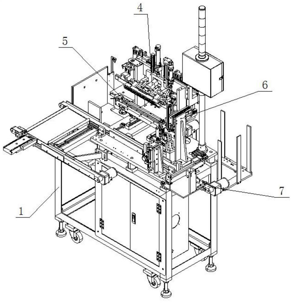
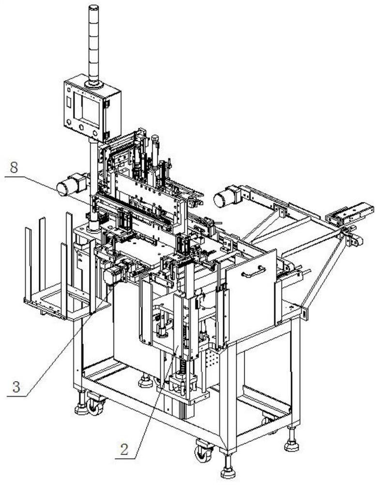
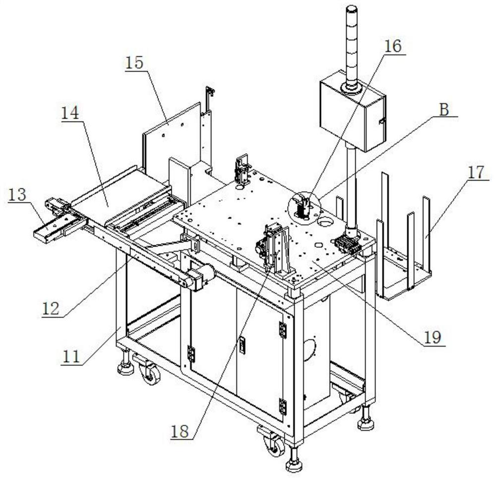
[0026] see Figure 1-8 , the present invention provides a technical solution: a motor rotor automatic feeding and positioning equipment, including a chassis assembly 1, the side of the chassis assembly 1 is provided with a screw lifting mechanism 2, and the upper end of the chassis assembly 1 is fixedly connected with a screw translation Mechanism 3, the upper end of the chassis component 1 is fixedly connected with a pneumatic rotary dismantling mechanism 4, ...


PUM


Abstract

An automatic feeding and positioning equipment for a motor rotor is disclosed. The automatic feeding and positioning equipment comprises a bottom frame assembly, a lead screw lifting mechanism is arranged on the side face of the bottom frame assembly, a lead screw translation mechanism is fixedly connected to the upper end of the bottom frame assembly, and a pneumatic rotary unstacking mechanism is fixedly connected to the upper end of the bottom frame assembly; the pneumatic rotary unstacking mechanism is located at the upper end of the lead screw translation mechanism, the upper end of the bottom frame assembly is fixedly connected with a first feeding conveying belt, the rear end of the pneumatic rotary unstacking mechanism is fixedly provided with a pneumatic gripper translation mechanism, and the upper end of the bottom frame assembly is fixedly connected with a pneumatic material taking and positioning mechanism; and the pneumatic material taking and positioning mechanism is located at the right end of the first feeding conveying belt, a second feeding conveying belt is fixedly installed on the inner side of the bottom frame assembly, and the upper end of the second feeding conveying belt is fixedly connected with the pneumatic material taking and positioning mechanism. According to the automatic feeding and positioning equipment for the motor rotor, through the materialdistributing and positioning equipment, the unstacking efficiency is greatly improved, and the accurate uniformity of the directivity of rotor feeding is guaranteed.

Description

technical field [0001] The invention relates to the technical field of motor rotor installation, in particular to an automatic feeding and positioning device for a motor rotor. Background technique [0002] Motor rotor: It is also a rotating part in the motor. The motor is composed of two parts: the rotor and the stator. It is used to realize the conversion device of electrical energy and mechanical energy and mechanical energy and electrical energy. The motor rotor is divided into a motor rotor and a generator rotor. [0003] However, the existing micro motors are assembled manually, which has low work efficiency, and manual deviations are likely to occur during the assembly process, which reduces the accuracy of the overall installation. Moreover, the existing micro motors are assembled manually, which is prone to errors. The situation of loading and missing loading reduces the overall processing and molding effect. Contents of the invention [0004] The purpose of the ...

Claims


Application Information

Patent Timeline
Patent Type & Authority Applications(China)
IPC IPC(8): H02K15/02B23P19/00B65G37/00B65G59/02B65G47/90B65G47/92
CPCB23P19/001B65G37/00B65G47/90B65G47/92B65G59/02H02K15/02
Inventor 赵欣龙永祥赖宁荣曾辉
Owner 赣州中科拓又达智能装备科技有限公司
Why Eureka
Try Eureka