Steel bar straightening machine for building machine

A steel bar straightening machine and construction machinery technology, which is applied in the direction of mechanical equipment, transmission parts, belts/chains/gears, etc., can solve the problems of conveying blockage, falling on it, and rough surface of steel bars, so as to avoid pollution, The effect of improving convenience

Inactive Publication Date: 2020-11-20
柏先琼
View PDF0 Cites 0 Cited by
  • Summary
  • Abstract
  • Description
  • Claims
  • Application Information

AI Technical Summary

Problems solved by technology

[0002] For the initial inspection of steel pipes to be straightened, steel bars with severe deformation, butt joint or flattening, and welded materials on the surface must be treated before straightening. These steel bars are generally straightened by means of friction, cutting, extrusion, etc. The surface of the steel bar after straightening is not only rough, but also has a large amount of powder remaining. The straightening machine adopts a chain transmission structure, so in the process, the powder on the top will fall on it, causing the problem of conveying blockage

Method used


Image

  • Steel bar straightening machine for building machine
  • Steel bar straightening machine for building machine
  • Steel bar straightening machine for building machine

Examples


Embodiment 1

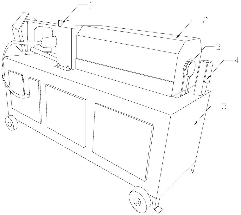
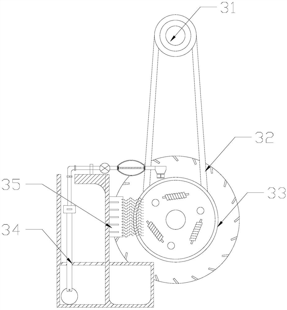
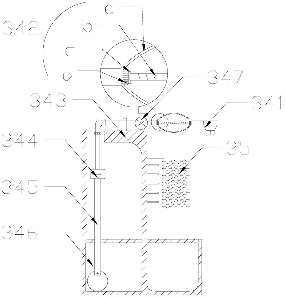
[0027] see Figure 1-Figure 5 , a steel bar straightening machine for construction machinery. The invention provides a steel bar straightening machine for construction machinery. Its structure includes a straightening seat 1, a steel bar delivery box 2, a transmission chain structure 3, a pillar 4, and a body 5. The top of the body 5 is equipped with a steel bar delivery box 2, a straightening seat 1 is installed on one side of the steel bar delivery box 2, and a transmission chain structure 3 is installed at the other end of the steel bar delivery box 2, and the transmission chain structure 3 is installed A pillar 4 is vertically installed on the top surface of the side of the body 5. The transmission chain structure 3 is composed of a secondary wheel 31, a transmission chain 32, a driving wheel 33, a lubricator 34, and a friction head 35. The driving wheel 33 is installed On the body 5, an auxiliary wheel 31 is arranged directly above the driving wheel 33, and the auxiliary ...

Embodiment 2

[0035] see Figure 1-Figure 5 , a steel bar straightening machine for construction machinery. The invention provides a steel bar straightening machine for construction machinery. Its structure includes a straightening seat 1, a steel bar delivery box 2, a transmission chain structure 3, a pillar 4, and a body 5. The top of the body 5 is equipped with a steel bar delivery box 2, a straightening seat 1 is installed on one side of the steel bar delivery box 2, and a transmission chain structure 3 is installed at the other end of the steel bar delivery box 2, and the transmission chain structure 3 is installed A pillar 4 is vertically installed on the top surface of the side of the body 5. The transmission chain structure 3 is composed of a secondary wheel 31, a transmission chain 32, a driving wheel 33, a lubricator 34, and a friction head 35. The driving wheel 33 is installed On the body 5, an auxiliary wheel 31 is arranged directly above the driving wheel 33, and the auxiliary ...


PUM


Abstract

The invention discloses a steel bar straightening machine for a building machine. The structure of the steel bar straightening machine comprises a straightening base, a steel bar conveying box, a conveying chain structure, a supporting column and a machine body. The steel bar conveying box is installed at the top end of the machine body. The straightening base is installed on one side of the steelbar conveying box. The conveying chain structure is installed at the other end of the steel bar conveying box. The supporting column is vertically installed on the top end face of the side, where theconveying chain structure is located, of the machine body. According to the steel bar straightening machine, after a valve is opened, an airbag is extruded, then lubricating oil is extracted from anoil chamber, then flows into a dropper and drops on a place where a conveying chain and a driving wheel are connected from top to bottom, lubricating is achieved, and the phenomenon of stoppage in thetransmission process is avoided; and the airbag is pinched with hands to extract the lubricating oil for lubricating, the airbag carries out lubricating through falling preventing rings, and when theairbag is pinched again, due to a stabilizing bar, the problem that due to excessive extrusion, bag skin is broken can be avoided.

Description

technical field [0001] The invention relates to the field of construction equipment, in particular to a steel bar straightening machine for construction machinery. Background technique [0002] For the initial inspection of steel pipes to be straightened, steel bars with severe deformation, butt joint or flattening, and welded materials on the surface must be treated before straightening. These steel bars are generally straightened by means of friction, cutting, extrusion, etc. The surface of the steel bar after straightening is not only rough, but also has a large amount of powder remaining. The straightening machine adopts a chain transmission structure, so in the process, the powder on the top will fall on it, causing the problem of conveying blockage. Contents of the invention [0003] Aiming at the deficiencies in the prior art, the present invention is realized through the following technical solutions: a steel bar straightening machine for construction machinery, it...

Claims


Application Information

Patent Timeline
Patent Type & Authority Applications(China)
IPC IPC(8): B21F1/02B21F11/00F16H57/05
CPCB21F1/02B21F11/00F16H57/042F16H57/0434F16H57/0435F16H57/0465F16H57/05
Inventor 柏先琼
Owner 柏先琼
Why Eureka
Try Eureka