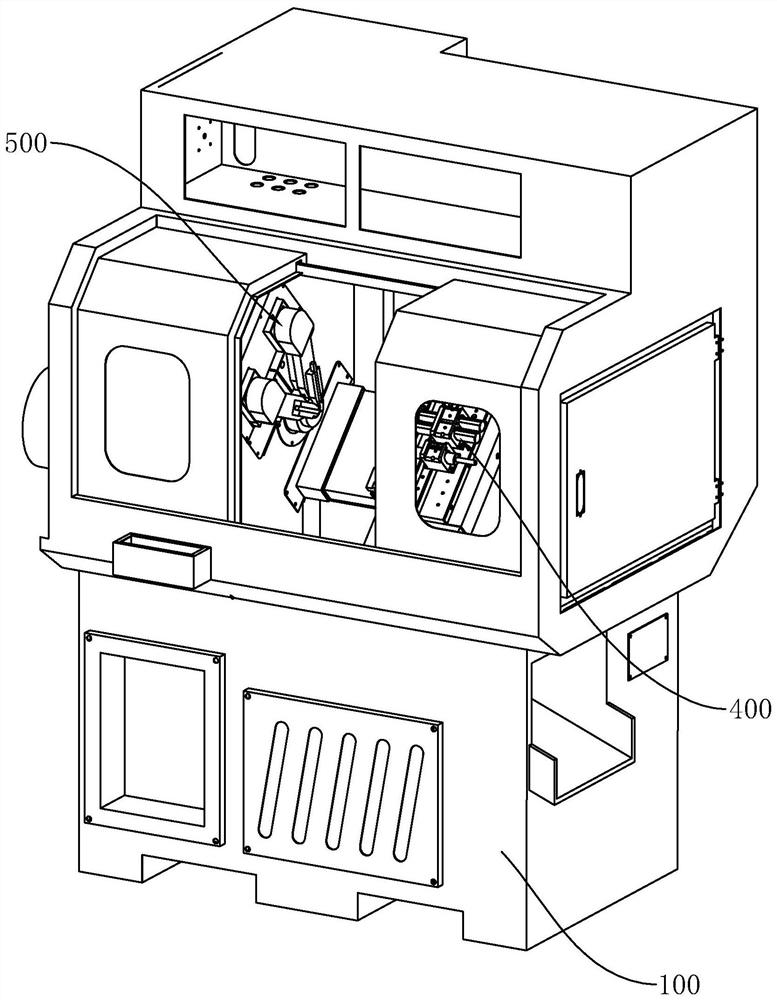
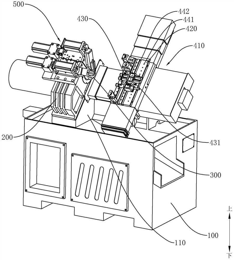
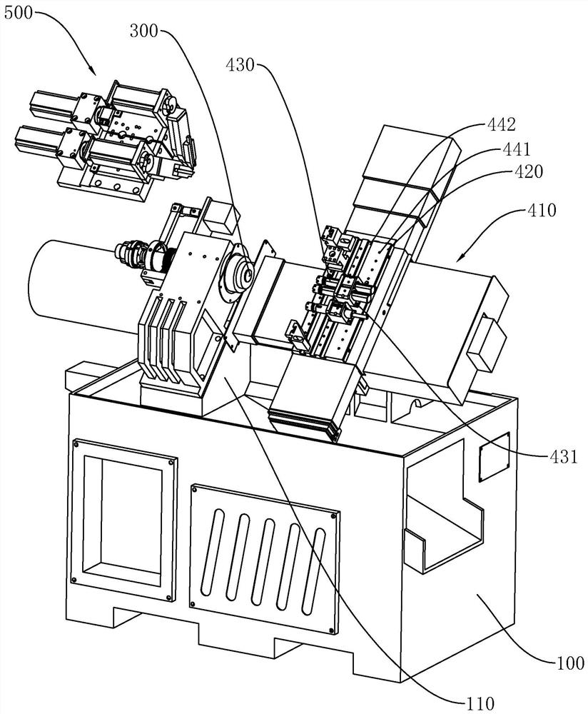
Multi-axis lathe

A multi-axis lathe and Z-axis technology, applied in the field of lathes, can solve problems such as unreasonable mechanism layout, poor flexibility of use, single processing method, etc., and achieve the effects of convenient lathe transformation, reasonable structure, and simplified NC programs

Pending Publication Date: 2020-11-20
中山市中台精密数控车床有限公司
View PDF1 Cites 2 Cited by
  • Summary
  • Abstract
  • Description
  • Claims
  • Application Information

AI Technical Summary

Problems solved by technology

[0002] The lathe is a relatively common machining equipment. The rotating workpiece is turned by the turning tool. The common lathe is only equipped with a single set of main machining tool mechanism, and the processing method is relatively simple. For this reason, there are currently many that are modified according to actual production needs. Axis lathes, such as the Chinese patent No. "201821741344.8" and the invention patent named "multi-axis CNC machine tool", disclose a lathe with multiple sets of feed tools, but due to the unreasonable layout of the mechanism, in addition to the main processing tool mechanism, other The feed tool can only realize radial feed. In the actual turning process, the workpiece is clamped and fixed. The tool that can only feed radially can only cut off or process small-width annular grooves. Although it is useful in some specific processing procedures, the scope of practical application is very narrow and the flexibility of use is poor.

Method used


Image

  • Multi-axis lathe
  • Multi-axis lathe
  • Multi-axis lathe

Examples


Embodiment Construction

[0038] Embodiments of the present invention are described in detail below, and examples of the embodiments are shown in the drawings, wherein the same or similar reference numerals denote the same or similar elements or elements having the same or similar functions throughout. The embodiments described below by referring to the figures are exemplary only for explaining the present invention and should not be construed as limiting the present invention.

[0039] In the description of the present invention, it should be understood that the orientation descriptions, such as up, down, front, back, left, right, etc. indicated orientations or positional relationships are based on the orientations or positional relationships shown in the drawings, and are only In order to facilitate the description of the present invention and simplify the description, it does not indicate or imply that the device or element referred to must have a specific orientation, be constructed and operated in ...


PUM


Abstract

The invention discloses a multi-axis lathe. The multi-axis lathe comprises a machine seat, a spindle mechanism, a main feed tool mechanism and at least one auxiliary feed tool mechanism. Each auxiliary feed tool mechanism comprises an X-axis drive mechanism, a Z-axis drive mechanism, a tool apron and a sliding table, wherein the sliding table comprises a bottom plate slidingly arranged on the sideface of a spindle seat and a feed plate, an included angle is formed between the bottom plate and the feed plate, the feed plate stretches towards a clamping jaw assembly along the end face of the spindle seat from the side face of the spindle seat, the tool apron is slidingly arranged on the feed plate, the X-axis drive mechanism is arranged on the sliding table and can drive the tool apron to move in the radial direction of the clamping jaw assembly, and the Z-axis drive mechanism is arranged on the spindle seat and can drive the sliding table to move in the axial direction of the clampingjaw assembly. Through the arrangement of the auxiliary feed tool mechanisms, the lathe can carry out multi-axis machining, the production efficiency is improved, through the reasonable arrangement ofthe sliding tables, the auxiliary feed tool mechanisms can achieve X-axis and Z-axis feed, the use flexibility is high, and the application range is wide.

Description

technical field [0001] The invention relates to the field of lathes, in particular to a multi-axis lathe. Background technique [0002] The lathe is a relatively common machining equipment. The rotating workpiece is turned by the turning tool. The common lathe is only equipped with a single set of main machining tool mechanism, and the processing method is relatively simple. For this reason, there are currently many that are modified according to actual production needs. Axis lathes, such as the Chinese patent No. "201821741344.8" and the invention patent named "multi-axis CNC machine tool", disclose a lathe with multiple sets of feed tools, but due to the unreasonable layout of the mechanism, in addition to the main processing tool mechanism, other The feed tool can only realize radial feed. In the actual turning process, the workpiece is clamped and fixed. The tool that can only feed radially can only cut off or process small-width annular grooves. Although it is useful i...

Claims


Application Information

Patent Timeline
Patent Type & Authority Applications(China)
IPC IPC(8): B23B3/30B23Q1/25
CPCB23B3/30B23Q1/25
Inventor 李德恒
Owner 中山市中台精密数控车床有限公司
Why Eureka
Try Eureka