NdFeB hydrogen decrepitation furnace

A hydrogen crushing furnace and NdFeB technology, which is applied in the field of NdFeB processing equipment, can solve the problems of affecting the processing quality of materials, occupying a large space, and inconvenience, so as to avoid contact between materials and excessive air, ensure processing quality, The effect of reducing volume

Pending Publication Date: 2021-11-09
BAIQIDA INTELLIGENT TECH NINGBO CO LTD
View PDF11 Cites 0 Cited by
  • Summary
  • Abstract
  • Description
  • Claims
  • Application Information

AI Technical Summary

Problems solved by technology

[0004] The defects of the above-mentioned hydrogen broken furnace are: firstly, the feed pipe and the discharge pipe are respectively arranged at both ends of the cylinder body. Since the discharge pipe needs to be connected to the receiving device, this kind of one-side feeding and one-side discharging The structure will make the overall volume of the equipment bulky, resulting in the need to occupy a large space, and the cylinder of the hydrogen breaker needs to be vacuumed for dehydrogenation during work (the hydrogen breaker for the hydrogenation of rare earth alloy powder is carried out by the gas pipeline. The material pipe vacuumizes the cylinder body), therefore, the requirements for the sealing of the cylinder body are relatively high. Since the above-mentioned hydrogen furnace breaks the feed pipe and the discharge pipe respectively at both ends of the cylinder body, the rear cover of the cylinder body needs to be frequently disassembled. Once the back cover of the cylinder and the discharge pipe are not tightly sealed, the external air will enter the cylinder from the gap between the back cover of the cylinder and the discharge pipe, and this part of the air will penetra

Method used


Image

  • NdFeB hydrogen decrepitation furnace
  • NdFeB hydrogen decrepitation furnace
  • NdFeB hydrogen decrepitation furnace

Examples


Embodiment Construction

[0062] The present invention will be further described below in conjunction with the accompanying drawings.

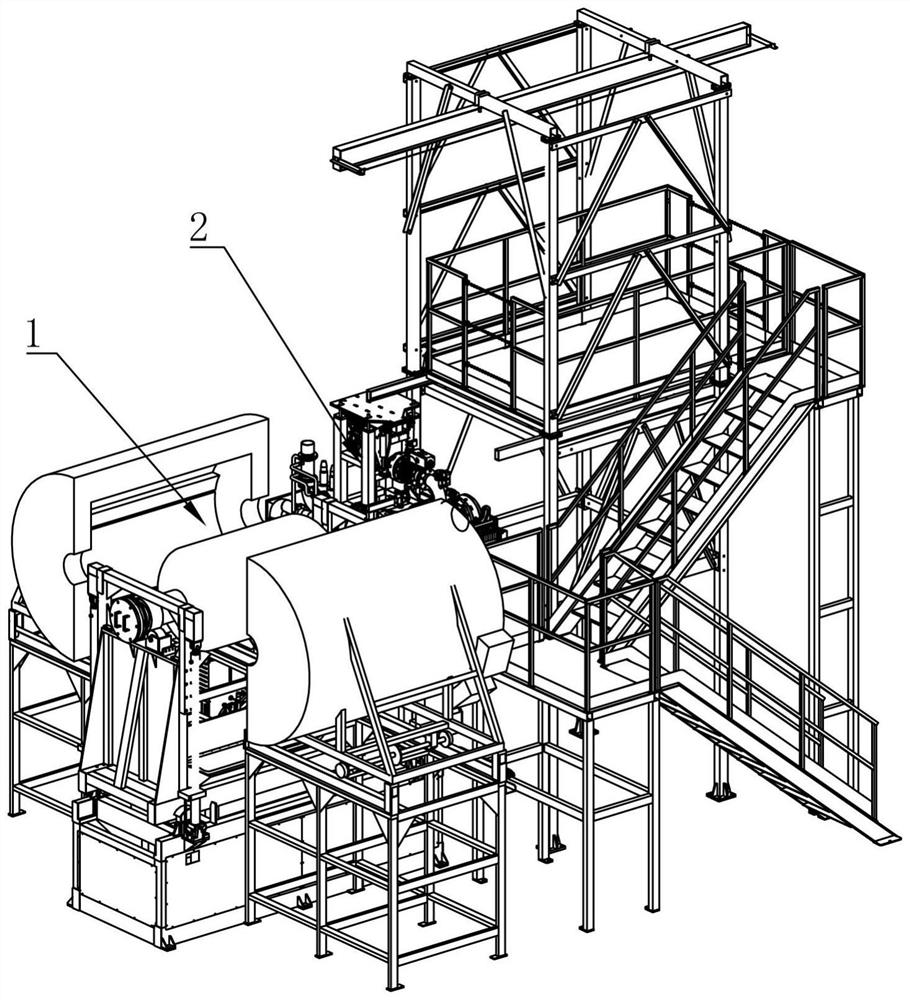
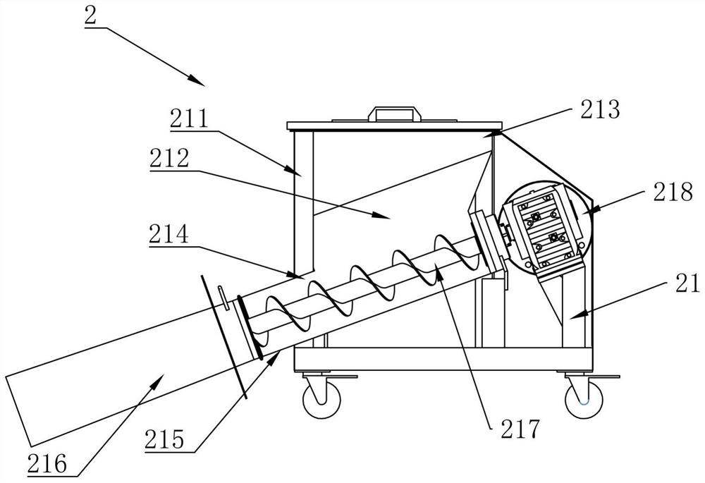
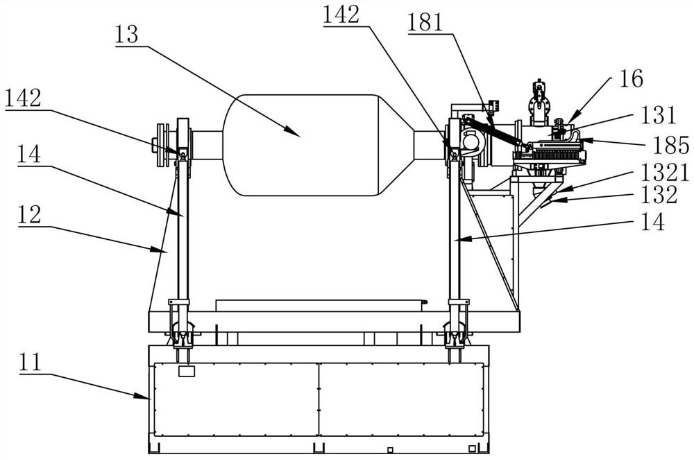
[0063] Such as Figure 1-17 The shown NdFeBH crushing furnace includes a host 1, a feeding device 2 and a vacuum system 3 that are arranged in conjunction with each other, wherein the host 1 includes a base 11, a first frame 12 and a cylinder 13, and the cylinder 13 is rotated and set On the first frame 12, the interior of the cylinder 13 is provided with an accommodating cavity for accommodating materials, and the cylinder 13 is respectively provided with a feed port 131 and a discharge port 132 communicating with the accommodating cavity. One end is an open end, and the other end is a closed end, and both the feeding port 131 and the feeding port 132 are located at the opening end of the cylinder body 13 . It should be noted that the "open end" defined above does not mean that the port of the cylinder 13 is always an open port, but that the inlet 131 and the outlet ...


PUM


Abstract

The invention discloses an NdFeB hydrogen decrepitation furnace which comprises a main machine, a feeding device and a vacuum system which are arranged in a matched mode, wherein the main machine comprises a base, a first rack and a barrel, the two ends of the first rack are movably connected with the base through jacking oil cylinders, the barrel is provided with a feeding port, a discharging port and a main pipeline connector, and the feeding port and the discharging port are located at the same end of the barrel; a feeding end cover is movably arranged on the first rack, a first locking flange assembly is movably arranged on the feeding port, and the feeding end cover is matched with the first locking flange assembly in an inserted mode; and the vacuum system comprises a second rack and a main pipeline movably arranged on the second rack, a second locking flange assembly is arranged at the end of the main pipeline, a connecting flange is arranged on a connector of the main pipeline, and the connecting flange is matched with the second locking flange assembly in an inserted mode. The NdFeB hydrogen decrepitation furnace is simple and reasonable in structure, convenient to operate, capable of effectively saving the space needed by installation, beneficial to improving the product quality and reducing the labor intensity of workers, and higher in reliability.

Description

technical field [0001] The invention relates to the technical field of NdFeB processing equipment, in particular to an NdFeB hydrogen crushing furnace. Background technique [0002] Hydrogen crushing furnace, also known as hydrogen crushing furnace, is a processing equipment for NdFeB alloy materials. Its principle is to use the characteristics of grain boundary fracture and transgrain boundary fracture produced by the rare earth permanent magnet alloy in the process of hydrogen absorption and dehydrogenation. Cause alloy pulverization, so as to obtain alloy powder with a certain particle size. After the NdFeB ingot is processed by the hydrogen crushing furnace, it directly enters the next process-jet mill crushing, which can effectively reduce the oxidation probability of the material. [0003] In the prior art, for example, Chinese Patent (Application No. 201020613042.X) discloses a hydrogen furnace for rare earth alloy powder hydrogenation, which includes a feeding devic...

Claims


Application Information

Patent Timeline
IPC IPC(8): B22F9/04
CPCB22F9/023B22F9/04Y02P10/20
Inventor 王兴杰周年生方辉鹤朱雄鹏郑科琦王晗权李军张雷李欢周文忠黄岳明周磊
Owner BAIQIDA INTELLIGENT TECH NINGBO CO LTD
Why Eureka
Try Eureka