Eureka AIR delivers breakthrough ideas for toughest innovation challenges, trusted by R&D personnel around the world.

Tool path planning and automatic avoidance control system based on workpiece clamping

An automatic avoidance and route planning technology, applied in the field of parts processing, can solve the problems of low processing efficiency and inability to process different parts in a targeted manner, and achieve the effect of improving processing efficiency

Active Publication Date: 2020-11-20
SHENYANG GUANGDA TECH DEV
View PDF9 Cites 2 Cited by
  • Summary
  • Abstract
  • Description
  • Claims
  • Application Information

AI Technical Summary

Problems solved by technology

[0008] Therefore, the present invention provides a tool path planning and automatic avoidance control system based on workpiece clamping to overcome the problem of low processing efficiency caused by the inability to perform fast and targeted processing on different parts in the prior art

Method used


Image

  • Tool path planning and automatic avoidance control system based on workpiece clamping
  • Tool path planning and automatic avoidance control system based on workpiece clamping

Examples


Embodiment Construction

[0058] In order to make the objects and advantages of the present invention clearer, the present invention will be further described below in conjunction with the examples; it should be understood that the specific examples described here are only for explaining the present invention, and are not intended to limit the present invention.

[0059] Preferred embodiments of the present invention are described below with reference to the accompanying drawings. Those skilled in the art should understand that these embodiments are only used to explain the technical principle of the present invention, and are not intended to limit the protection scope of the present invention.

[0060] It should be noted that, in the description of the present invention, terms such as "upper", "lower", "left", "right", "inner", "outer" and other indicated directions or positional relationships are based on the terms shown in the accompanying drawings. The direction or positional relationship shown is ...


PUM


Abstract

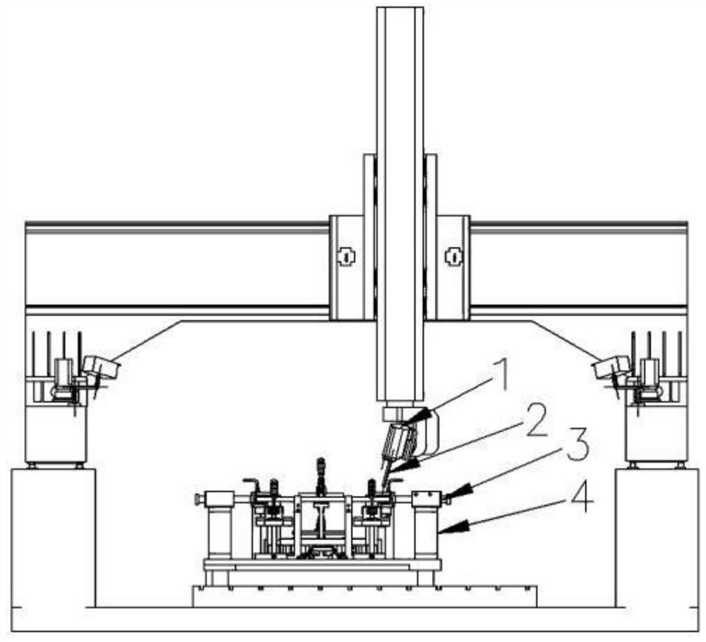
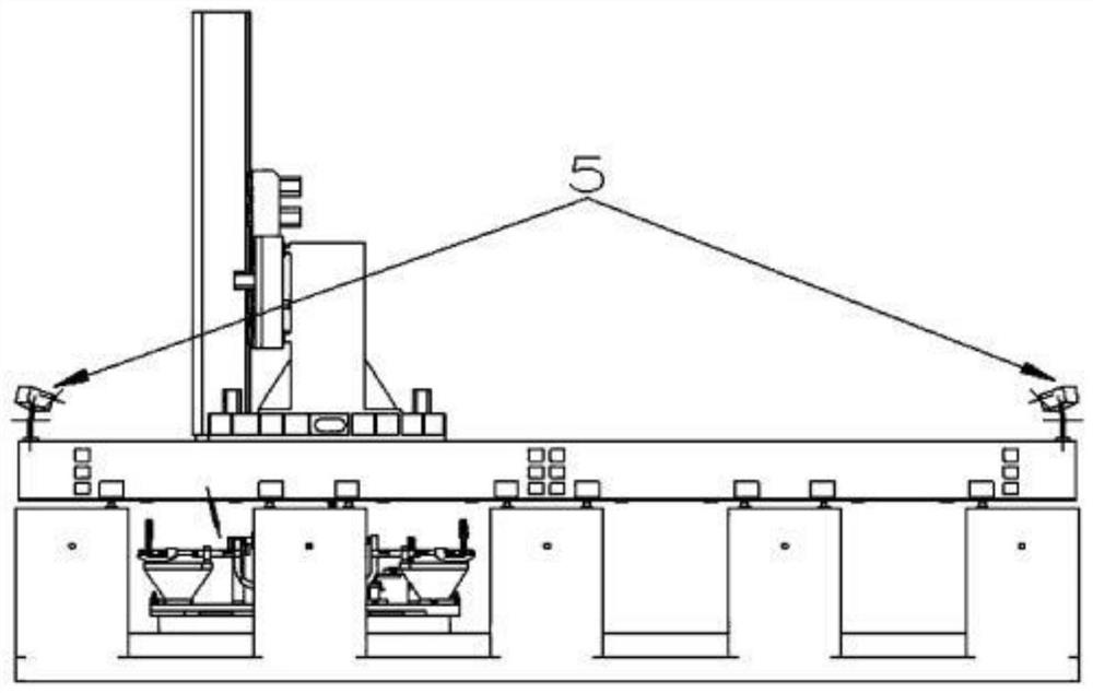
The invention relates to a tool path planning and automatic avoidance control system based on workpiece clamping. The tool path planning and automatic avoidance control system based on workpiece clamping comprises a tool module, a clamping module and a control module, wherein the control module is connected with a main shaft and automatic avoidance clamp heads correspondingly and is used for limiting starting of the system and selecting a corresponding machining mode and a corresponding avoiding mode according to the specific model of a part to be machined so that the tool module can machine the part to be machined and the clamping module can achieve avoidance when the tool module performs machining. According to the tool path planning and automatic avoidance control system based on workpiece clamping, the model of the part to be machined is judged by using matrixes in a U0 matrix group, corresponding machining matrixes are selected from an A0 matrix group according to the judgment result, and corresponding avoidance matrixes are selected from an R0 matrix group, so that clamps complete avoidance to a main shaft tool in the system machining process, the pertinence of the system formachining different parts can be improved, and then the machining efficiency of the system for the part is further improved.

Description

technical field [0001] The invention relates to the technical field of parts processing, in particular to a tool path planning and automatic avoidance control system based on workpiece clamping. Background technique [0002] In the CNC machining process, especially the CNC machining of large and medium-sized plate-shaped parts, fixtures are usually used to fix the workpiece to be processed on the operating platform. , usually it is necessary to stop the machine tool first, and then manually remove the fixture, and then stop the machine after the section has been processed, manually tighten the fixture, and continue the processing work. The fixation of a large workpiece often requires multiple fixtures. Every time the tool is close to the fixture, the fixture needs to be moved away manually to avoid it. This will inevitably cause machining interruption and affect machining efficiency and quality. In the current high-speed machining environment, This effect is more prominent....

Claims


Application Information

Patent Timeline
Patent Type & Authority Applications(China)
IPC IPC(8): B23Q17/22B23Q15/013G05B19/19
CPCB23Q15/013B23Q17/2208G05B19/19
Inventor 秦广财张斌
Owner SHENYANG GUANGDA TECH DEV
Why Eureka
Eureka Blog
Learn More