Extrusion molding mold for automatic coating of wires and cables

A technology for covering wires and cables, which is applied in the manufacture of household appliances, other household appliances, cables/conductors, etc. It can solve the problems of potential safety hazards for burn workers, insufficient covering, and poor covering effect of wires and cables. Increase the coating effect, avoid burns, and reduce the effect of operating safety hazards

Inactive Publication Date: 2020-11-20
福州约春向科技有限公司
View PDF0 Cites 5 Cited by
  • Summary
  • Abstract
  • Description
  • Claims
  • Application Information

AI Technical Summary

Problems solved by technology

[0002] Plastic extrusion dies are a type of molds used to form continuous-shaped plastic products, also known as extrusion molding heads, which are widely used in the processing of wire and cable coating layers. At present, workers need to wrap the wire and cable during coating operations Only by pinching the beginning of the coating with your hands can the subsequent coating be carried out smoothly. Because the coating layer that is not completely solidified has a high temperature during the coating operation, there is a safety hazard of scalding the operator, and the current coating operation is Use the gravity of the covering layer to automatically attach to the wire and cable, so that the covering effect of the wire and cable is not good, and the covering is not tight enough

Method used


Image

  • Extrusion molding mold for automatic coating of wires and cables
  • Extrusion molding mold for automatic coating of wires and cables
  • Extrusion molding mold for automatic coating of wires and cables

Examples


Embodiment Construction

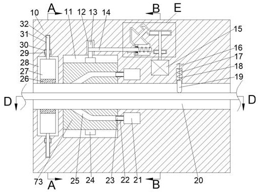
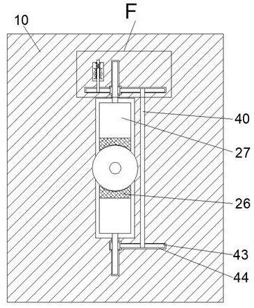
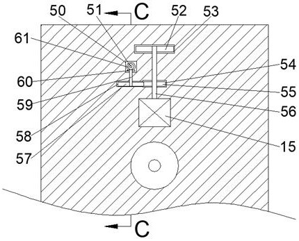
[0019] Combine below Figure 1-7 The present invention is described in detail, wherein, for the convenience of description, the orientations mentioned below are defined as follows: figure 1 The up, down, left, right, front and back directions of the projection relationship itself are the same.

[0020] An extrusion mold for automatically covering wires and cables described in conjunction with accompanying drawings 1-7 includes a main box body 10, and a cable delivery cavity 20 is provided through the left and right sides of the main box body 10, and the cable delivery cavity The upper and lower sides of 20 are connected with up and down symmetrical lifting chambers 28, and the lifting chamber 28 is far away from the cable conveying chamber 20. A nut rotating chamber 30 is arranged in the side end wall, and the nut rotating chamber 30 is far away from the cable conveying chamber. 20 is provided with a slide bar chamber 31 extending through the nut rotating chamber 30 to the li...


PUM


Abstract

The invention relates to the field of plastic molds, and discloses an extrusion molding mold for automatic coating of wires and cables. The extrusion molding mold includes a main box body, a cable conveying cavity is formed in the main box body in a left-right penetrating mode, lifting cavities in upper-lower symmetric are formed in the upper side and the lower side of the cable conveying cavity in a communicating mode, nut rotating cavities are formed in the end walls of the sides, away from the cable conveying cavity, of the lifting cavities, and sliding rod cavities are formed in the side,away from the cable conveying cavity, of the nut rotating cavities, wherein the sliding rod cavities extend in the direction of the side close to the cable conveying cavity and penetrate through the nut rotating cavities into the lifting cavities. A mechanism is used for clamping the head of a coating layer to instead of manually pinching by hand, so that an operator is prevented from the risks ofscalding, the potential safety hazard of worker is greatly reduced, meanwhile, a rotating coating mechanism enables the wires and cables to be coated more tighter, the coating effect is greatly increased, meanwhile, according to the diameter of the wires and cables, the rotation speed of the coating layer is automatically adjusted, and thus it is ensured that the coating layers of the wires and cables of different diameters can achieve a tight coating effect.

Description

technical field [0001] The invention relates to the field of plastic molds, in particular to an extrusion mold used for automatic coating of electric wires and cables. Background technique [0002] Plastic extrusion dies are a type of molds used to form continuous-shaped plastic products, also known as extrusion molding heads, which are widely used in the processing of wire and cable coating layers. At present, workers need to wrap the wire and cable during coating operations Only by pinching the beginning of the coating with your hands can the subsequent coating be carried out smoothly. Because the coating layer that is not completely solidified has a high temperature during the coating operation, there is a safety hazard of scalding the operator, and the current coating operation is The gravity of the coating layer is used to automatically attach to the wire and cable, so that the coating effect of the wire and cable is not good, and the coating is not tight enough. Cont...

Claims


Application Information

Patent Timeline
Patent Type & Authority Applications(China)
IPC IPC(8): B29C48/06B29C48/154B29C48/30H01B13/14H01B13/24B29L31/34
CPCB29L2031/3462B29C48/06B29C48/154B29C48/30H01B13/14H01B13/24
Inventor 高哲磊
Owner 福州约春向科技有限公司
Why Eureka
Try Eureka