Pull lifting platform for railway rescue

A technology of traction lifting and platform, which is applied in the direction of lifting frames, railway car body parts, railway auxiliary equipment, etc., and can solve problems such as poor rescue conditions, short skylight period, and inconvenience of normal railway running

Pending Publication Date: 2020-11-20
SHANDONG LINGONG CONSTR MACHINERY
View PDF0 Cites 4 Cited by
  • Summary
  • Abstract
  • Description
  • Claims
  • Application Information

AI Technical Summary

Problems solved by technology

Therefore, when the construction equipment breaks down on the railway line, due to the short skylight period (maintenance time) of the railway, generally about 2 hours, the rescue condition is poor and the time is insufficient, causing inconvenience to the normal operation of the railway

Method used


Image

  • Pull lifting platform for railway rescue
  • Pull lifting platform for railway rescue
  • Pull lifting platform for railway rescue

Examples


Embodiment 1

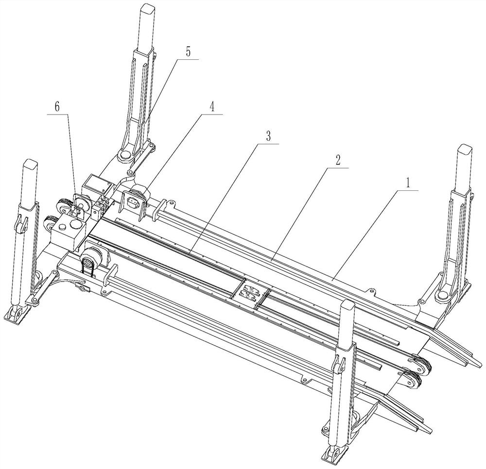
[0041] like figure 1 As shown, a traction lifting platform for railway rescue includes a platform 1, and the platform 1 is provided with a track 2, a traction mechanism 3, a walking device 4, a folding outrigger lifting mechanism 5 and a control system 6, and the control system 6 They are respectively connected with the traction mechanism 3, the running gear 4 and the folding outrigger lifting mechanism 5.

Embodiment 2

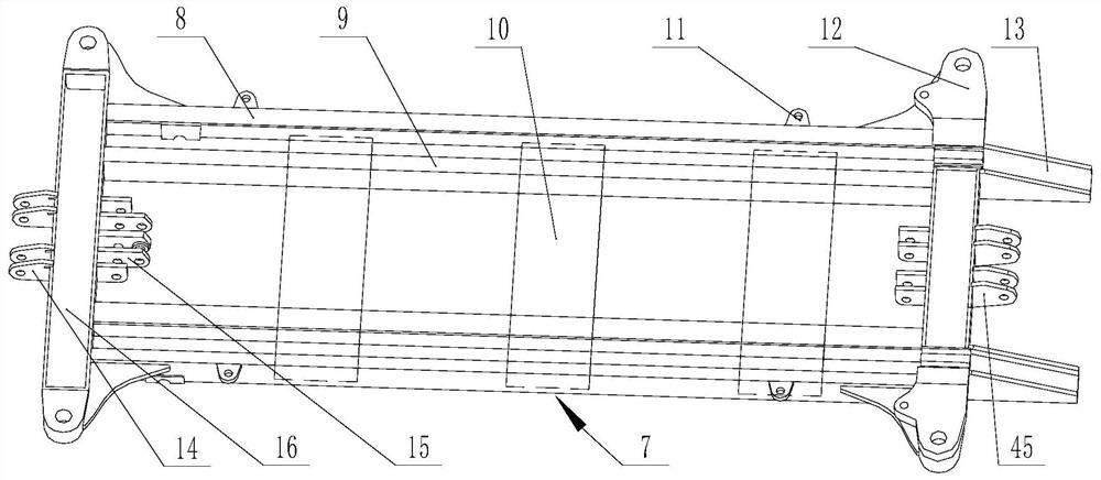
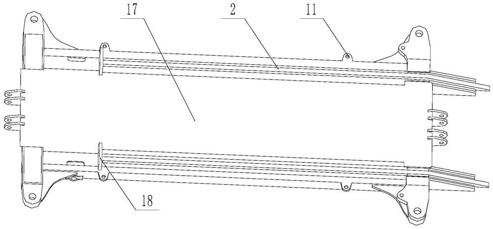
[0043] A traction lifting platform for railway rescue, such as figure 2 and image 3 As shown, the platform 1 includes a frame main plate 7, and the frame main plate 7 includes a rectangular tube A8, a rectangular tube B9, a bottom plate 10 and a channel steel 16, and the rectangular tube A8, the rectangular tube B9, the bottom plate 10 and the channel steel 16 form a frame structure, which has Sufficient bearing capacity, the frame body plate 7 is welded with a leg mount 12 , a top plate 17 , a pulley seat and an oil cylinder seat 15 .

[0044] Platform 1 is the installation platform for other equipment and also the carrier for transporting rescue equipment. Its width is less than the maximum width of 3000mm of the flatbed truck, and its length is in accordance with the needs of transporting rescue equipment. The track 2 is welded on the platform 1, and the width of the track 2 is consistent with that of the railway track.

[0045] like Figure 4-8As shown, the traction m...

Embodiment 3

[0053] A traction lifting platform for railway rescue, the locking mechanism includes a locking rod 44, and a locking rod mounting seat 11 cooperating with the locking rod 44 is also provided on the main body plate 7 of the frame. like Figure 13 As shown, the folding leg lifting mechanism 5 performs folding and lifting actions, and is symmetrically installed on the front and rear parts of the platform 1 through the pin shaft 43 and the locking rod 44. Internal sliding; the outrigger frame 41 can be opened or folded as required, and locked with the locking lever 44 .

[0054] The locking type of the folding outrigger lifting mechanism 5 is a rigid pull rod, which will Figure 15 The pin shafts at both ends of the locking rod 44 shown are inserted into the mounting holes of the locking rod mounting base 11 for locking. The structure is simple, but manual installation is required. Other parts are identical with embodiment 2.


PUM


Abstract

The invention discloses a pull lifting platform for railway rescue, which belongs to the technical field of engineering machinery and solves the defect that inconvenience is caused to normal running on railway as a result of a poor rescue working condition while conventional construction equipment in the prior art has faults on the railway. The pull lifting platform is characterized in that a mainbody structure comprises a platform, wherein a rail, a pull mechanism, a travelling device, a folding supporting leg lifting mechanism and a control system are arranged on the platform; and the control system is separately connected to the pull mechanism, the travelling device and the folding supporting leg lifting mechanism. The pull lifting platform is mainly used for pulling down constructionequipment with faults from the railway.

Description

Technical field: [0001] The invention belongs to the technical field of construction machinery, and in particular relates to a traction lifting platform for railway rescue. Background technique: [0002] At present, small-scale railway construction and maintenance equipment appears on the railway instead of manpower. The weight of these equipment ranges from a few tons to dozens of tons. The transfer of maintenance construction equipment from the ground to the rail requires transitional road surfaces, making transitional platforms or finding the nearest level crossing. After the equipment is shut down due to a railway failure, it is necessary to find a lifting device to hoist the faulty equipment away from the railway. When the distance to the station is relatively close, the steel wheel brake can also be released for short-distance traction into the auxiliary road of the station. [0003] However, the existing technology has high requirements on the transportation and rescu...

Claims


Application Information

Patent Timeline
Patent Type & Authority Applications(China)
IPC IPC(8): B66F7/20B66F7/28B66F3/46F15B21/08B61D15/00B61K13/00
CPCB61D15/00B61K13/00B66F3/46B66F7/20B66F7/28F15B21/087
Inventor 夏兆沂陈亮邵珠娜严志远徐涛
Owner SHANDONG LINGONG CONSTR MACHINERY
Why Eureka
Try Eureka