
Vortex air floatation device

A vortex air flotation and air intake hood technology, which is used in flotation water/sewage treatment, chemical instruments and methods, water/sludge/sewage treatment, etc. problem, to achieve the effect of small bubble diameter, good air flotation effect, and slow floating speed

Inactive Publication Date: 2020-11-20
ZHEJIANG YONGLI ENVIRONMENTAL PROTECTION EQUIP
View PDF5 Cites 0 Cited by
  • Summary
  • Abstract
  • Description
  • Claims
  • Application Information

AI Technical Summary

Problems solved by technology

[0003] The present invention overcomes the shortcomings of large bubble diameter and small number of bubbles produced by the air flotation device, and poor effect on sewage treatment, and provides a vortex air flotation device, which produces small diameter bubbles and large number of bubbles during its working process. Good effect on sewage treatment

Method used


Image

  • Vortex air floatation device
  • Vortex air floatation device
  • Vortex air floatation device

Examples


Embodiment 1

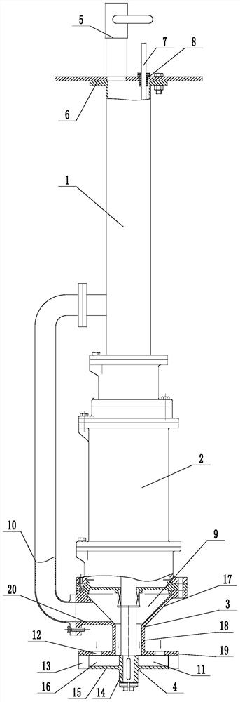
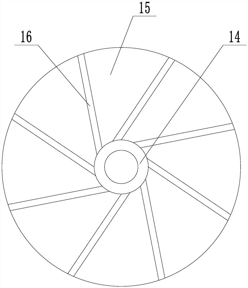
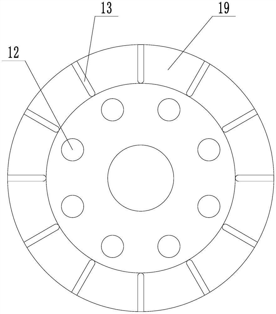
[0026] Embodiment 1: A kind of vortex air flotation device (see attached figure 1 To attach image 3 ), including installation sleeve 1, power motor 2, intake cover 3, impeller 4, the power motor is a submersible motor, the power motor is installed at the lower end of the installation sleeve, the intake cover is installed at the lower end of the power motor, and the upper end of the installation sleeve is installed with air volume Regulating valve 5, the upper end of the installation sleeve is tightly connected to the support plate 6, the support plate is provided with an air inlet hole and a cable installation hole, the air volume regulating valve is installed on the air inlet hole, and the cable 7 is tightly connected in the cable installation hole. A sealing sleeve 8 is installed between the cable and the cable installation hole. The upper end of the installation sleeve is placed above the water surface, and the impeller is placed in the water. The air intake cover is pro...

Embodiment 2

[0029] Embodiment 2: A kind of vortex air flotation device (see attached Figure 4 To attach Figure 6), its structure is similar to that of Embodiment 1, the main difference is that in this embodiment, a rotating shaft 21 is installed between two adjacent fixed blades on the intake cover, and three driving blades 22 are evenly distributed on the outer wall of the rotating shaft, and the driving blades are installed on The outer edge of the impeller cavity. Several through holes 23 are arranged on the driving blade. The through holes can not only shear the air bubbles, but also help reduce the resistance to the outward flow of the gas-liquid mixture. A shaking plate 24 is installed between two adjacent rotating blades on the cover plate, and a number of shear holes 25 are densely covered on the shaking plate. A pair of splints 26 are arranged at both ends of the shaking plate on the cover plate, and both ends of the shaking plate are installed on the two splints. Between, t...


PUM


Abstract

The invention discloses a vortex air floatation device, and aims to overcome the defects that bubbles generated by an air floatation device are large in diameter, the number of the bubbles is small, and the sewage treatment effect is poor. The device comprises a mounting bushing, a power motor, an air inlet cover and an impeller, wherein the power motor is mounted at the lower end of the mountingbushing, the air inlet cover is mounted at the lower end of the power motor, an air inlet cavity is formed in the air inlet cover, an air inlet pipe is communicated between the air inlet cavity and the mounting bushing, the output shaft of the power motor penetrates out of the air inlet cover, the impeller is mounted on the output shaft of the power motor, an impeller cavity is formed between theimpeller and the air inlet cover, the air inlet cavity is communicated with the impeller cavity, a water inlet hole communicated with the impeller cavity is formed in the air inlet cover, and a plurality of fixing blades are arranged on the outer edge of the impeller cavity on the air inlet cover. According to the invention, bubbles generated in the working process of the vortex air flotation device are small in diameter, the floating speed is low, the number of the bubbles is large, and the sewage treatment effect is good.

Description

technical field [0001] The invention relates to an air flotation technology, more specifically, it relates to a vortex air flotation device. Background technique [0002] Air flotation is a dissolved air system that produces a large number of fine bubbles in water, so that the air is attached to the suspended particles in the form of highly dispersed tiny bubbles, resulting in a state of density lower than that of water. The principle of buoyancy is used to make it float on the water surface, thereby realizing solid-liquid Separated water treatment equipment. Many air flotation devices currently in use produce larger diameter bubbles, fewer bubbles, short contact time between bubbles and suspended solids, and poor treatment effect. Contents of the invention [0003] The present invention overcomes the shortcomings of large bubble diameter and small number of bubbles produced by the air flotation device, and poor effect on sewage treatment, and provides a vortex air flotat...

Claims


Application Information

Patent Timeline
Patent Type & Authority Applications(China)
IPC IPC(8): C02F1/24
CPCC02F1/24C02F2201/002
Inventor 郦智明郦苏浩宋立斌赵一书许国富
Owner ZHEJIANG YONGLI ENVIRONMENTAL PROTECTION EQUIP
Learn More