License plate recognition method and device
A recognition method and license plate technology, applied in the field of license plate recognition method and its device, can solve problems such as injuries and achieve the effect of reducing injuries
- Summary
- Abstract
- Description
- Claims
- Application Information
AI Technical Summary
Problems solved by technology
Method used
Image

Examples
Embodiment 1
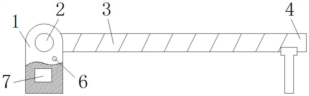
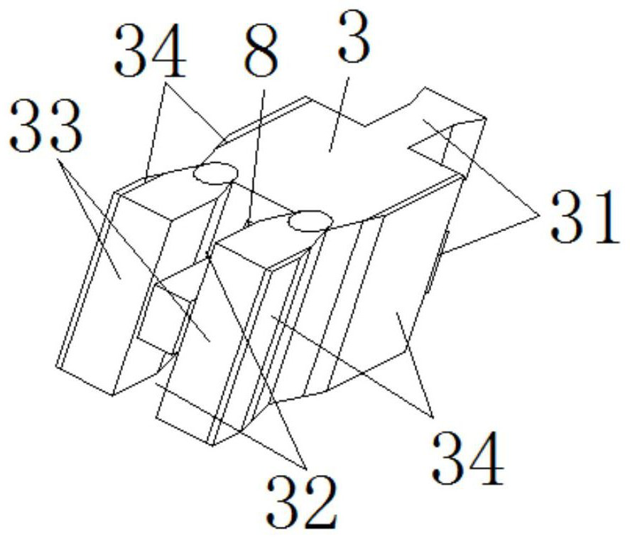
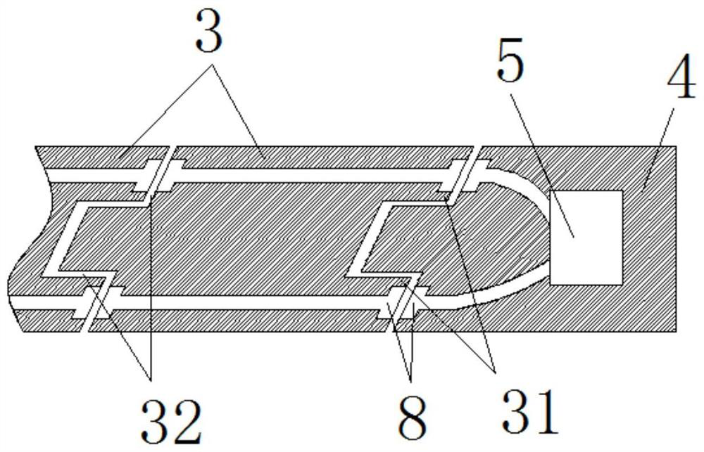
[0019] see Figure 1-3 , the present embodiment provides a license plate recognition method and device thereof, comprising a main body 1, a processor 7 and an access control rotating motor 2 are arranged on the main body 1, and an access control connection block 3 is fixed on one side of the access control rotation motor 2, and the access control connection block 3. There are several pieces, and the left and right sides are respectively provided with a card block 31 and a card slot 32. The access control connection block 3 is connected to each other through the card block 31 and the card slot 32. The joint between the card block 31 and the card slot 32 is fixed with a conductive connection. Block 8, the adjacent access control connection block 3 joints are equipped with stopper 33 by spring rotation, the rear end of the most end access control connection block 3 is clamped with outer end block 4 by clamping block 31, draw-in groove 32, and the inner end block 4 Set siren 5.
...
Embodiment 2
[0024] see Figure 1-4 , made further improvements on the basis of Embodiment 1: the main body 1 is provided with a sensor 6, the sensor 6 is connected to the processor 7 through a wire, the left and right sides of the access control connection block 3 are fixed with reflective paper 34, and the stopper 33 Be arranged on both sides of the block 31 and the slot 32, the front end of the block 31 and the inboard of the slot 32 are all arranged in a matching trapezoid, the alarm 5 is connected to the processor 7 by a conductive connection block 8 and a wire, and the processor 7 It is connected with the access control rotating motor 2 through wires, and a control button 9 is arranged outside the main body 1, and the control button 9 is connected with the access control rotating motor 2 through wires.
[0025] In this embodiment, when it is necessary to open the access control, a remote controller matching it is set outside the sensor 6, and a signal is sent by the remote control, a...
PUM
 Abstract
Description
Claims
Application Information
PatSnap Eureka turns technology decisions into work you can execute. Powered by our Innovation Knowledge Graph, it runs expert workflows across engineering, life sciences, materials and intellectual property. Get your review-ready output in minutes.


