Ceramic impeller fixing device, ceramic impeller, and manufacturing method and detachment method for ceramic impeller

A technology for fixing devices and impellers, which is applied in the direction of manufacturing tools, ceramic molding machines, and parts of pumping devices for elastic fluids, etc. Problems such as poor metal bonding

Pending Publication Date: 2020-11-20
ANDRITZ CHINA
View PDF1 Cites 3 Cited by
  • Summary
  • Abstract
  • Description
  • Claims
  • Application Information

AI Technical Summary

Problems solved by technology

[0006] Although ceramic pumps are a good direction, most of the impellers of ceramic pumps on the market have problems such as weak combination of metal and ceramics, unchanged disassembly, and insufficient strength of ceramic blades.
[0007] In the Chinese utility model patent document entitled "A Composite Ceramic Impeller Containing a Metal Skeleton" and the publication number is "CN210196121U", a ceramic composite impeller is disclosed. Although the overall strength of the impeller is improved, in the metal skeleton, only The use of perforated plates as the blades and rear cover does not further optimize the structure of the metal skeleton, and there is still the problem that the metal skeleton and ceramics are not firmly bonded
[0008] Therefore, it is desired to provide a ceramic impeller suitable for pumping fluids containing hard particles and corrosives in power plants to solve the problems of poor bonding between ceramics and metals, insufficient strength of ceramic impellers during operation, and easy damage to ceramics during disassembly and maintenance. , at the same time, it is also hoped that the pumping efficiency of the ceramic impeller can be further improved

Method used


Image

  • Ceramic impeller fixing device, ceramic impeller, and manufacturing method and detachment method for ceramic impeller
  • Ceramic impeller fixing device, ceramic impeller, and manufacturing method and detachment method for ceramic impeller
  • Ceramic impeller fixing device, ceramic impeller, and manufacturing method and detachment method for ceramic impeller

Examples


Embodiment Construction

[0033] The ceramic impeller provided by the present invention will be described in detail below in conjunction with the accompanying drawings. The accompanying drawings and embodiments cannot be understood as limiting the present invention.

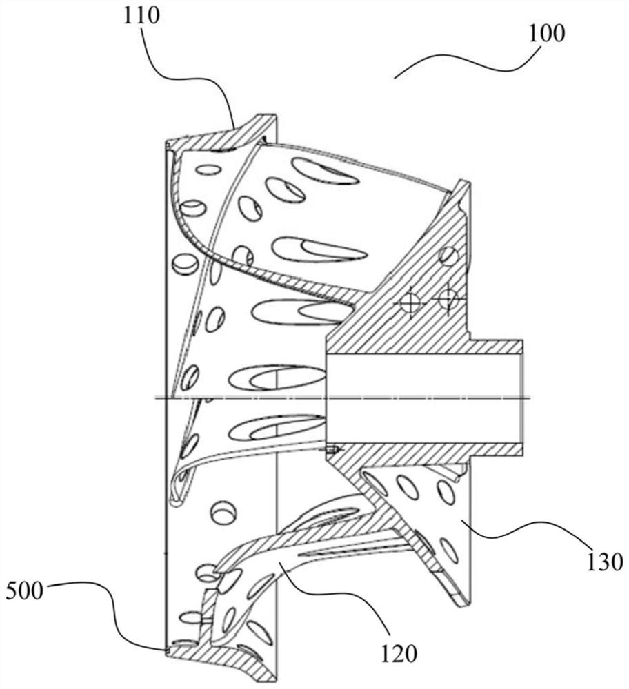
[0034] figure 1 Illustrates the metal skeleton of the ceramic impeller provided by the present invention, such as figure 1 As shown, the metal frame 100 in the ceramic impeller provided by the present invention includes a front cover 110, a rear cover 130, and blades 120 arranged between the front cover 110 and the rear cover 130.

[0035] The ceramic layer is formed on the metal skeleton 100 by vacuum casting to form the ceramic impeller of the present invention.

[0036] Wherein, a groove 500 is provided on the end side of the front cover 110 of the metal skeleton 100 to hold the ceramic layer cast on the metal skeleton. The grooves are usually arranged on the end faces of the front and rear cover plates so that the ceramic layer A metal skele...


PUM


Abstract

The invention relates to a ceramic impeller which comprises a metal framework and a ceramic layer formed on the metal framework in a vacuum casting mode. The metal framework comprises a front cover plate, a rear cover plate and blades arranged between the front cover plate and the rear cover plate; the front cover plate, the rear cover plate and the blades of the metal framework are provided withthrough holes respectively, and the through holes are used for fixedly holding the ceramic layer of the ceramic impeller; the front cover plate or the rear cover plate of the metal framework is also provided with at least one of reinforcing ribs, notches and grooves for fixedly holding the ceramic layer poured on the metal framework. The invention also relates to a manufacturing method for the ceramic impeller. The manufacturing method comprises the following steps of carrying out three-dimensional modeling on the metal framework in industrial software, wherein it is ensued that the strength and stress of the ceramic impeller runs are met all the time when a pump through simulation calculation and analysis of different working conditions; providing the metal framework analyzed through simulation calculation; and vacuum-casting the ceramic layer on the metal framework.

Description

Technical field [0001] The invention relates to a ceramic impeller and a manufacturing method thereof, in particular to a ceramic impeller for transporting hard particles and corrosive fluids in a power plant and a manufacturing method thereof. The invention also relates to a ceramic impeller fixing device and a ceramic impeller disassembly method. Background technique [0002] In the process of flue gas desulfurization in power plants, because the medium to be pumped contains hard particles and highly corrosive components, there are high requirements on the materials of the pump. The existing material applications are as follows: [0003] The first is the metal material, which must be duplex stainless steel or super duplex stainless steel. The disadvantage of duplex stainless steel or super duplex stainless steel is that the cost is very high. In addition, the wear resistance and corrosion resistance of stainless steel materials are still far behind ceramic materials. [0004] Sec...

Claims


Application Information

Patent Timeline
Patent Type & Authority Applications(China)
IPC IPC(8): F04D29/22F04D29/24F04D29/20F04D29/02B28B23/02B28B3/00
CPCB28B3/006B28B23/02F04D29/026F04D29/20F04D29/2216F04D29/2227F04D29/242
Inventor 邓晓明邹礼生
Owner ANDRITZ CHINA
Why Eureka
Try Eureka