Check valve with low flow resistance

A valve flap, valve cover technology, applied in the direction of lift valve, valve details, control valve, etc., can solve problems such as affecting the service life of the pipeline, threatening the safety of the pipeline, large water hammer effect, etc., to reduce the water hammer effect and reduce the instantaneous Differential pressure, the effect of reducing the risk of cracking

Active Publication Date: 2020-11-20
NINGBO JIEKELONG PRECISION MFG
View PDF10 Cites 3 Cited by
  • Summary
  • Abstract
  • Description
  • Claims
  • Application Information

AI Technical Summary

Problems solved by technology

In order to reduce the flow resistance, the gap between the valve disc and the valve body must be increased. When the diameter of the water hole is fixed, the outer diameter of the valve disc is fixed, which can only be realized by increasing the inner diameter of the valve, which increases the cost and affects the installation.
When the fluid is passed in or cut off, the disc opens / closes non-linearly, and the instantaneous pressure difference between the front of the valve and the back of the valve is large, which will produce a large water hammer effect, which seriously threatens the safety of the pipeline and affects the service life of the pipeline.

Method used


Image

  • Check valve with low flow resistance
  • Check valve with low flow resistance
  • Check valve with low flow resistance

Examples


Embodiment Construction

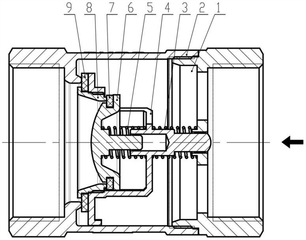
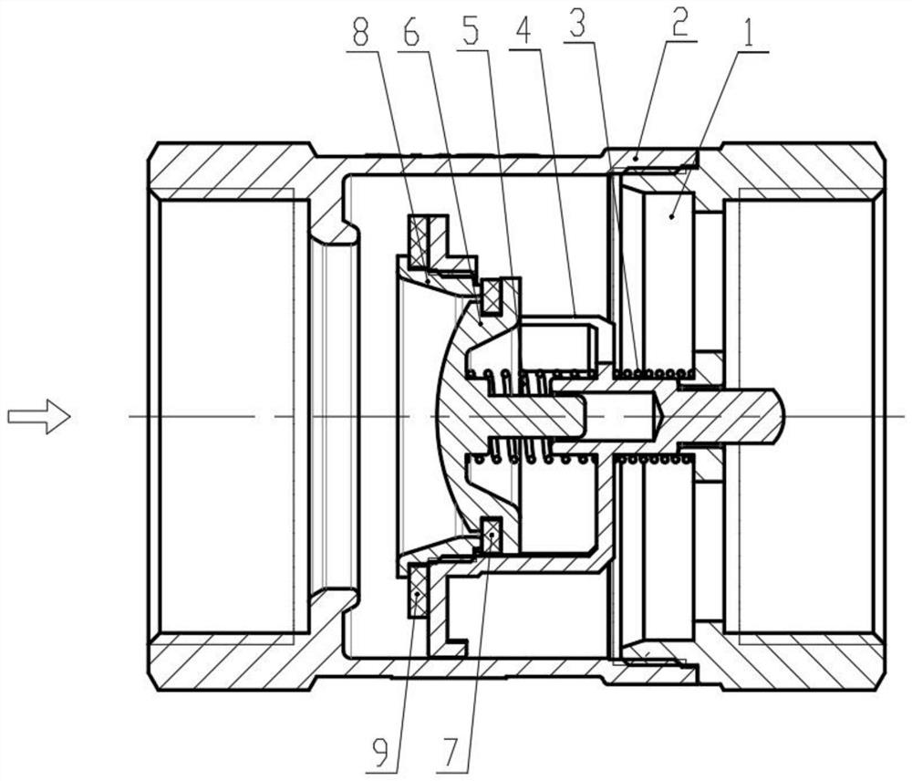
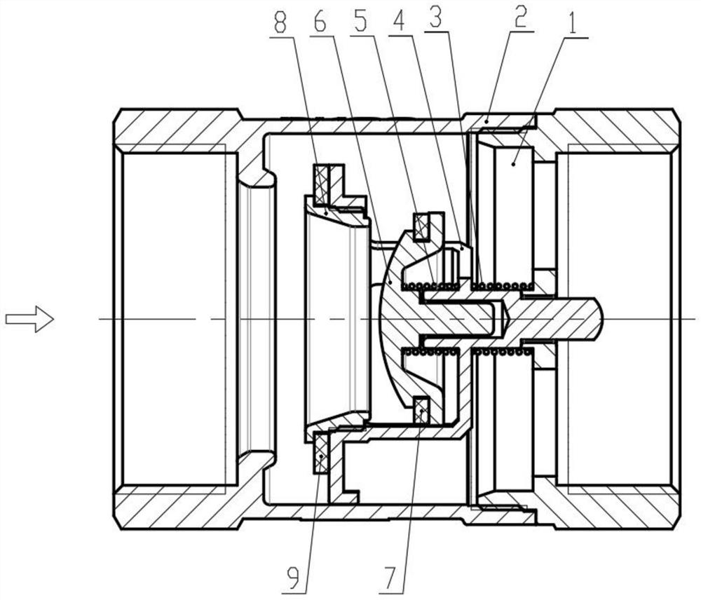
[0033] In order to make it easy to understand the technical means, creative features, goals and effects achieved by the present invention, the following examples are combined with the appended figure 1 To attach Image 6 A low-flow anti-return valve provided by the present invention is described in detail.

[0034] The serial numbers assigned to the components in this document, such as "first", "second", etc., are only used to distinguish the described objects and do not have any sequence or technical meaning. The "connection" and "connection" mentioned in this application all include direct and indirect connection (connection) unless otherwise specified. In describing the present invention, it is to be understood that the terms "upper", "lower", "front", "rear", "left", "right", "vertical", "horizontal", "top", The orientation or positional relationship indicated by "bottom", "inner", "outer", "clockwise", "counterclockwise", etc. is based on the orientation or positional r...


PUM


Abstract

The invention discloses a check valve with low flow resistance, and belongs to the technical field of valve devices. The check valve with the low flow resistance comprises a valve body, a valve deck and a valve element assembly; a cavity is formed inside the valve body, and a first through hole communicating with the cavity is formed in one end of the valve body; the valve deck is connected with the other end of the valve body, and a main through hole communicating with the cavity is formed in the valve deck; the valve element assembly is arranged in the cavity, one end of the valve element assembly is connected with the valve deck through a first elastic component, and the valve element assembly can reciprocate in the telescopic direction of the first elastic component; the valve elementassembly comprises a valve clack cover, a valve clack support and a valve clack, the valve clack cover is provided with a through second through hole communicating with the cavity, one side of the valve clack cover is connected with the valve clack support, the valve clack support is provided with a plurality of secondary through holes communicating with the cavity, the valve clack is arranged inan inner cavity of the valve clack support, one end of the valve clack is connected with the valve clack support through a second elastic component, and the valve clack can reciprocate in the telescopic direction of the second elastic component. The check valve with the low flow resistance is small in size, good in check effect and low in resistance.

Description

technical field [0001] The invention relates to the technical field of valve devices, in particular to a low-flow preventing return valve. Background technique [0002] Check valve is also known as check valve, back pressure valve or one-way valve. The main function of check valve is to prevent the medium from flowing backward. The check valve is an automatic valve, which is automatically opened or closed by the thrust of the medium flow in the pipeline. The disc of the opening and closing part of the check valve reciprocates along the central axis of the valve body, and the disc of the check valve can be provided with a spring to realize quick closing. During the long-term use of the existing check valve disc, the sealing pair is subject to long-term wear and tear by the medium, which is prone to the problem of reduced pressure bearing capacity or even damage, resulting in a reduced service life of the valve. The valve disc crosses the valve body, and the fluid can only b...

Claims


Application Information

Patent Timeline
Patent Type & Authority Applications(China)
IPC IPC(8): F16K15/06F16K1/44F16K47/02
CPCF16K15/066F16K1/44F16K47/023
Inventor 郭理军严荣杰蔡小飞
Owner NINGBO JIEKELONG PRECISION MFG
Why Eureka
Try Eureka