Fixing device used for gas pipeline along-bridge laying

A technology for fixing devices and gas pipelines, applied in the direction of cleaning methods using gas flow, pipeline supports, pipeline protection, etc., can solve the problems of different pipeline sizes, the influence of gas pipeline fixing, etc., and achieve the effect of increasing the flow speed

Inactive Publication Date: 2020-11-20
张文勇
View PDF18 Cites 2 Cited by
  • Summary
  • Abstract
  • Description
  • Claims
  • Application Information

AI Technical Summary

Problems solved by technology

A gas pipeline fixing device in the above-mentioned patent has the following disadvantages: when the existing device fixes the gas pipeline, it may affect the fixing of the gas pipeline due to the different sizes of the pipelines

Method used


Image

  • Fixing device used for gas pipeline along-bridge laying
  • Fixing device used for gas pipeline along-bridge laying
  • Fixing device used for gas pipeline along-bridge laying

Examples


Embodiment 1

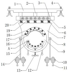
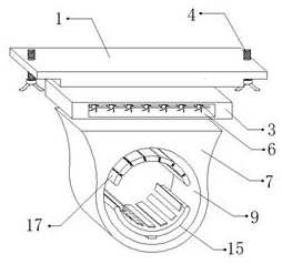
[0029] refer to Figure 1-3 , a fixing device for laying a gas pipeline with a bridge, comprising a mounting base 1, a plurality of fixed shafts 2 are connected to the bottom outer wall of the mounting base 1 through bolts, and a fixed plate 3 is connected to the bottom outer wall of the fixed shaft 2 through bolts, The bottom outer wall of the fixed plate 3 is connected with a plurality of second springs 19 by bolts, and the bottom outer wall of the second spring 19 is connected with a support plate 7 by bolts, and one side outer wall of the support plate 7 is provided with a fixed opening 9, and the fixed opening 9 A plurality of first springs 18 are connected to the top inner wall by bolts, and a clamping mechanism 17 is connected to one side of the outer wall of the first springs 18 by bolts. The clamping mechanism 17 is composed of multiple clamping blocks, and two adjacent clamping blocks The blocks are connected by elastic parts, and the bottom outer wall of the clampin...

Embodiment 2

[0038] refer to Figure 4 , a fixing device for laying gas pipelines with bridges. Compared with Embodiment 1, the outer walls of both sides of the support plate 7 are connected with arc-shaped plates 24 by bolts, and the bottom outer walls of the arc-shaped plates 24 are set There are a plurality of buffer pads 25 , the bottom outer wall of the buffer pad 25 is provided with a pressing plate 26 , and the bottom outer wall of the pressing plate 26 is provided with a brush plate 27 .

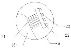
[0039] Working principle: When in use, the device is fixed on the bridge through the mounting base 1 and the fixing bolt 4. When the gas pipeline needs to be fixed, the gas pipeline is inserted inside the fixed port, and the clamping mechanism 17 and the first spring 18 are used to fix the device on the bridge. , The third spring 21 and the splint 15 can effectively fix the gas pipeline according to the size of the gas pipeline, and turn the stop bolt 13 to fix the gas pipeline. The friction for...


PUM


Abstract

The invention discloses a fixing device used for gas pipeline along-bridge laying. The fixing device comprises a mounting seat. The outer wall of the bottom of the mounting seat is fixedly connected with multiple fixed shafts, and the outer walls of the bottoms of the fixed shafts are fixedly connected with a fixed plate. The outer wall of the bottom of the fixed plate is fixedly connected with multiple second springs, and the outer walls of the bottoms of the second springs are fixedly connected with a supporting plate. A fixed opening is formed on the outer wall of one side of the supportingplate, the inner wall of the top of the fixed opening is fixedly connected with multiple first springs, and the outer walls of one sides of the first springs are fixedly connected with a clamping mechanism. The clamping mechanism is composed of multiple clamping blocks, and every two adjacent clamping blocks are connected through an elastic part. According to the fixing device, a gas pipeline canbe effectively fixed, the surface of the gas pipeline can be prevented from being corroded, the situation that dust adheres to the outer wall of the gas pipeline, and consequently the surface of thegas pipeline is corroded can be avoided, and the situation that the gas pipeline is damaged due to the fact that heavy objects fall onto the gas pipeline can be avoided.

Description

technical field [0001] The invention relates to the technical field of gas pipeline erection, in particular to a fixing device for laying a gas pipeline along a bridge. Background technique [0002] When the gas pipeline passes through the river, there are currently three methods: crossing the river bottom; laying with the bridge, or using the pipe bridge to cross. The advantage is that the cost is low, and it is convenient for inspection and maintenance. When the gas pipeline is laid along with the bridge, the gas pipeline must be fixed by a fixing device, so as to improve the safety of the gas pipeline erection. [0003] After retrieval, the Chinese patent authorization number is CN207961746U, which discloses a gas pipeline fixing device, including a mounting seat, a mounting cavity is provided on the mounting seat, a rear cover is provided at the bottom of the mounting cavity, and a rear cover is provided on the upper part of the mounting cavity. There is a bayonet socke...

Claims


Application Information

Patent Timeline
Patent Type & Authority Applications(China)
IPC IPC(8): F16L3/11F16L55/035F16L57/00F16L58/00B08B5/02A01M29/16
CPCA01M29/16B08B5/02F16L3/11F16L55/035F16L57/00F16L58/00
Inventor 张文勇
Owner 张文勇
Why Eureka
Try Eureka