Solid waste incineration device based on environmental protection technology

A solid waste and incineration device technology, applied in incinerators, combustion types, combustion methods, etc., can solve problems such as environmental pollution, human injury, and large smoke, and achieve the effect of improving incineration effect, avoiding impact, and effectively incinerating

Pending Publication Date: 2020-11-20
上海智密技术工程研究所有限公司
View PDF3 Cites 3 Cited by
  • Summary
  • Abstract
  • Description
  • Claims
  • Application Information

AI Technical Summary

Problems solved by technology

Existing waste incineration devices not only have low incineration efficiency, but also produce relatively large smoke after incinerat

Method used


Image

  • Solid waste incineration device based on environmental protection technology
  • Solid waste incineration device based on environmental protection technology
  • Solid waste incineration device based on environmental protection technology

Examples


Example Embodiment

[0023] Example 1

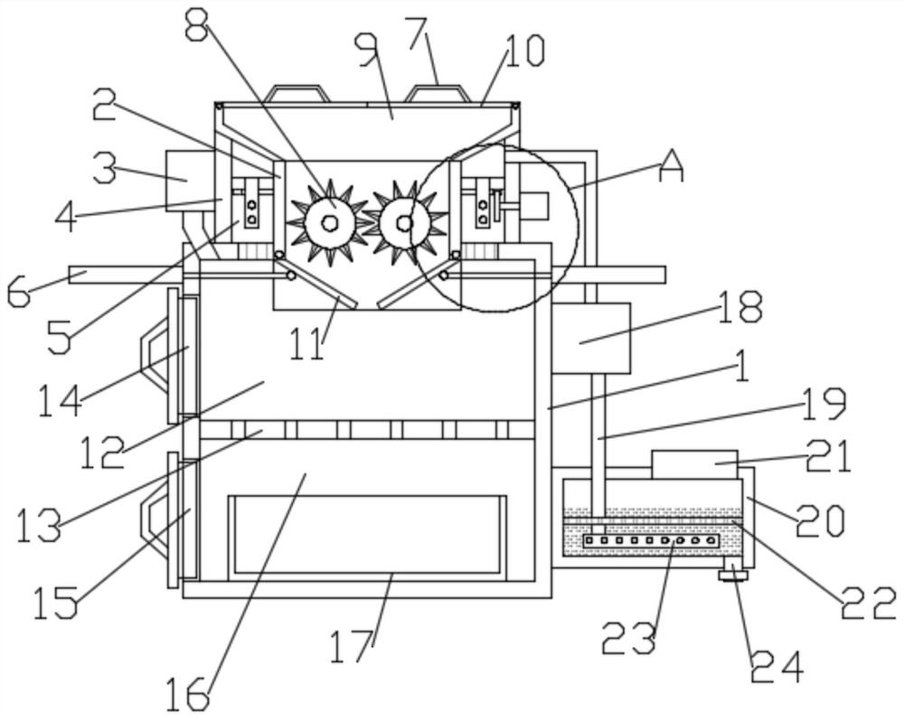
[0024] Such as figure 1 As shown, in the embodiment provided by the present invention, a solid waste incineration device based on environmental protection technology includes an incineration box 1, and the inner cavity of the incineration box 1 is divided into an incineration cavity 12 by an incineration plate 13 provided. And the upper and lower chambers of the collection chamber 16, and the collection chamber 16 is provided with a collection frame 17 directly below the incineration plate 13;

[0025] The upper side of the incineration box 1 is provided with a first window cover 14 corresponding to the incineration cavity 12; the lower side of the incineration box 1 is provided with a second window cover corresponding to the collection cavity 16 Window cover 15;

[0026] Further, the top fixing frame of the incineration box 1 is provided with a crushing drum 2, and the top of the crushing drum 2 is provided with a dropping funnel 9. The top of the dropping funnel...

Example Embodiment

[0030] Example 2

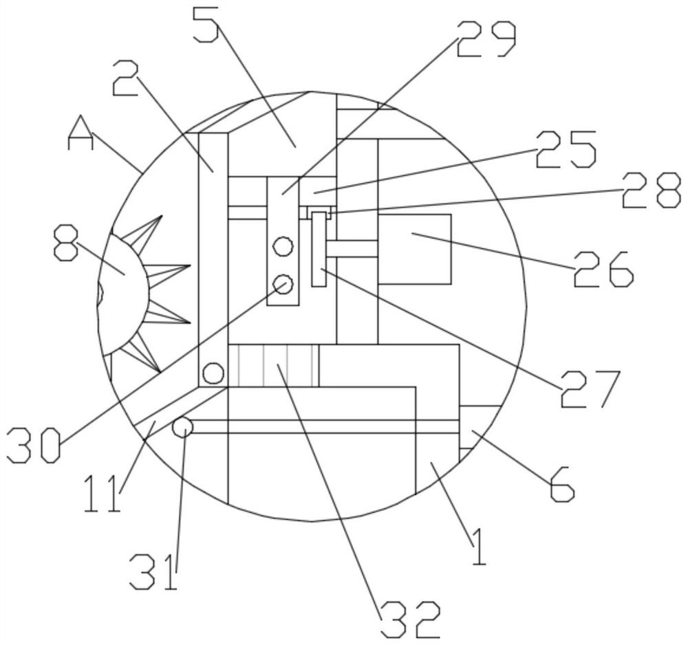
[0031] Such as Figure 1-3 As shown, different from Embodiment 1, in the embodiment provided by the present invention, the air purification assembly includes an air purification box 20 fixedly installed on the outer wall of the incineration box body 1, and the top of the air purification box 20 has exhaust Port 21, the inner cavity of the air purification box 20 is fixed with an air distribution ring tube 23, and the air inlet end of the air distribution ring tube 23 communicates with the upper cavity of the insulation ring cavity 5 through the air outlet pipe 19, wherein the first 2. The air pump 18 is fixedly installed on the air outlet pipe 19;

[0032] Further, in the embodiment provided by the present invention, the air purification box 20 is also provided with a dispersing mesh plate 22 located above the air distribution ring pipe 23, which can prevent upward escaping in the air purification box 20 The gas is broken up to make it more fully react with the...


PUM


Abstract

The invention relates to the field of garbage disposal, and particularly discloses a solid waste incineration device based on an environmental protection technology. The solid waste incineration device comprises an incineration box body, wherein an inner cavity of the incineration box body is divided into an upper cavity and a lower cavity, namely an incineration cavity and a collection cavity, through an arranged incineration plate; a crushing cylinder is fixedly erected at the top of the incineration box body; and a pair of incineration rollers driven by a motor are further arranged in the crushing cylinder. According to the incineration device provided by an embodiment of the invention, the solid waste is firstly crushed through a crushing roller in the crushing cylinder, so that the incineration effect of the solid waste entering the incineration cavity can be effectively improved, hot air generated during combustion in the incineration cavity enters a thermal insulation ring cavity through a vent hole; when the hot air is filled in the thermal insulation ring cavity, the solid waste in the crushing cylinder can be preheated and dried, so that the crushed solid waste enters theincineration cavity and can be more effectively incinerated; and the exhaust gas produced in an incineration process is ultimately treated through an air purification component.

Description

Technical field [0001] The invention relates to the field of garbage treatment, in particular to a solid garbage incineration device based on environmental protection technology. Background technique [0002] Garbage is a solid waste produced in human daily life and production. Because of its large discharge volume, complex and diverse composition, and pollution, resource and social nature, it needs to be harmless, resourced, reduced and socialized. If it is not handled properly, it will pollute the environment, affect environmental health, waste resources, undermine the safety of production and life, and undermine social harmony. Garbage disposal is to remove the garbage quickly, carry out harmless treatment, and finally make reasonable use of it. The widely used garbage disposal methods today are sanitary landfill, high-temperature composting and incineration. The purpose of garbage disposal is harmlessness, resource utilization and reduction. Existing garbage incinerators n...

Claims


Application Information

Patent Timeline
IPC IPC(8): F23G5/033F23G5/44F23G5/04F23J15/06F23J15/00B01D53/78
CPCF23G5/033F23G5/44F23G5/04F23J15/06F23J15/006B01D53/78
Inventor 赵梓迪
Owner 上海智密技术工程研究所有限公司
Why Eureka
Try Eureka