
High-power high-energy electron irradiation station based on irradiation linear accelerator

A linear accelerator and high-energy electron technology, applied in the field of irradiation stations, can solve the problems of low overall efficiency, low utilization rate, and large cargo volume, and achieve the effect of improving irradiation efficiency and safe dose rate

Pending Publication Date: 2020-11-20
SHANGHAI SINOTEX HIGH ENERGY TECH
View PDF0 Cites 1 Cited by
  • Summary
  • Abstract
  • Description
  • Claims
  • Application Information

AI Technical Summary

Problems solved by technology

[0008] Although the irradiation capacity of the irradiation station can be improved to a certain extent and a certain degree of redundancy can be ensured, the cost of the independent protective building, the independent under-beam transportation line and the turning mechanism is extremely high, and it is limited by turning over. The efficiency of the surface mechanism, its radiation efficiency is not too high
[0009] But at present, a considerable part of the cargo is large in size, and the 10MeV energy electron beam cannot completely penetrate, and in order to ensure the uniformity of the beam, most of the cargo requires double-sided irradiation in the irradiation process, so the output of the irradiation station The transportation line is generally equipped with a turning mechanism, and the turning mechanism can only turn over the box-type goods or hard-packed goods, and can't do anything for soft-packed goods. It can only be turned over manually. The overall efficiency is low and the failure rate is high. Use low rate

Method used


Image

  • High-power high-energy electron irradiation station based on irradiation linear accelerator
  • High-power high-energy electron irradiation station based on irradiation linear accelerator

Examples


Embodiment approach

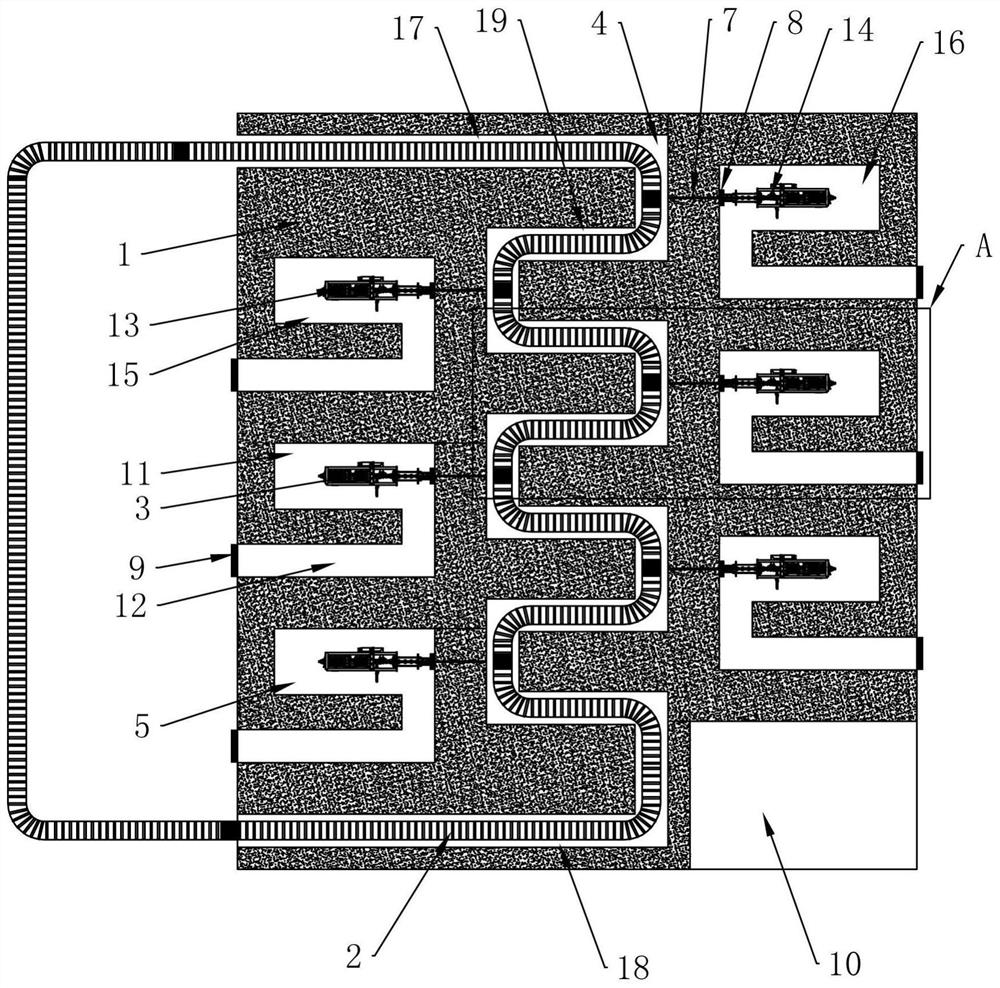
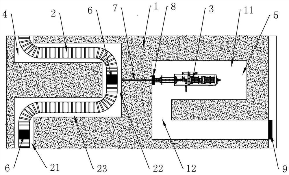
[0041] In further embodiments of the present invention, please continue to refer to Figure 1 to Figure 2As shown, several accelerator chambers 5 located on both sides of the radiation protection building 1 are arranged at intervals. Preferably, the irradiation of the linear accelerators 3 on both sides of the radiation protection building 1 can be prevented from facing each other, and the staggered arrangement can improve safety.

[0042] In a further embodiment of the present invention, protective doors 9 are provided at the entrances and exits of several accelerator chambers 5 .

[0043] In a further embodiment of the present invention, the high-power and high-energy electron irradiation station further includes: a control system, the control system is arranged in the radiation protection building 1 , and the control system is signal-connected to a plurality of linear accelerators 3 respectively.

[0044] In a further embodiment of the present invention, a plurality of win...


PUM


Abstract

The invention discloses a high-power high-energy electron irradiation station based on an irradiation linear accelerator. The station comprises a ray protection building which is internally provided with a transportation channel and a plurality of accelerator chambers communicated with the transportation channel, wherein the plurality of accelerator chambers are located at two sides of the transportation channel; a under-beam conveying line which penetrates through the conveying channel, and is used for conveying a plurality of to-be-irradiated cargoes; and a plurality of linear accelerators which are arranged in the plurality of accelerator chambers respectively, wherein the plurality of linear accelerators respectively face the under-beam conveying line, and the plurality of linear accelerators are respectively used for carrying out double-sided irradiation on the two sides of the plurality of to-be-irradiated cargoes on the under-beam conveying line. The two sides of the goods on the under-beam conveying line are subjected to double-face irradiation through the linear accelerators, a turnover mechanism is not needed, the cost is reduced, and the irradiation efficiency is improved.

Description

technical field [0001] The invention relates to the technical field of irradiation stations, in particular to a high-power and high-energy electron irradiation station based on an irradiation linear accelerator. Background technique [0002] The operation of the high-energy electron irradiation station requires fast in and out of the goods to be irradiated. One is to meet the rapid listing of goods (especially living consumables), and the other is to reduce the storage demand of the irradiation station and prevent the backlog of goods from causing the irradiation station to explode. Warehouse, explosion machine, reduce the process time of the goods to be irradiated in the irradiation station, and improve customer satisfaction. [0003] To satisfy the fast in and out of the goods to be irradiated, the accelerator beam power of the electron irradiation station must be sufficient (the irradiation dose of different goods is constant, the greater the accelerator power, the shorte...

Claims


Application Information

Patent Timeline
Patent Type & Authority Applications(China)
IPC IPC(8): G21K5/10H05H7/00H05H9/00
CPCG21K5/10H05H7/00H05H9/00
Inventor 谭松清王复涛张海龙封淼伟单云叶斌王凤涛黄敬松赵平徐粒峰
Owner SHANGHAI SINOTEX HIGH ENERGY TECH
Learn More