High-efficiency solar cell panel and mounting structure thereof

A technology of solar panels and installation structures, applied in solar thermal power generation, solar thermal energy, solar collectors, etc., can solve the problems of easy damage to the structure of the house, inconvenient fixing and removal, and affecting the power generation efficiency of the power generation panel, etc., to achieve convenience Effect of installation and disassembly, improvement of power generation efficiency

Active Publication Date: 2020-11-20
安徽联维新能源科技有限公司
View PDF7 Cites 3 Cited by
  • Summary
  • Abstract
  • Description
  • Claims
  • Application Information

AI Technical Summary

Problems solved by technology

[0003] Existing, the existing household solar power generation equipment generally consists of solar panels and mounting brackets. It is fixed to the roof, and the drilling operation is easy to damage the structure of the house, and it is not convenient to remove the fixing frame from the roof after fixing. At the same time, when snow or dust accumulates on the solar panel, it will affect the power generation efficiency of the power generation panel. Therefore, , we propose a high-efficiency solar panel and its mounting structure

Method used


Image

  • High-efficiency solar cell panel and mounting structure thereof
  • High-efficiency solar cell panel and mounting structure thereof
  • High-efficiency solar cell panel and mounting structure thereof

Examples


Embodiment Construction

[0026] In order to make the technical means, creative features, goals and effects achieved by the present invention easy to understand, the present invention will be further described below in conjunction with specific embodiments.

[0027] In the description of the present invention, it should be noted that the terms "upper", "lower", "inner", "outer", "front end", "rear end", "both ends", "one end", "another end" The orientation or positional relationship indicated by etc. is based on the orientation or positional relationship shown in the drawings, and is only for the convenience of describing the present invention and simplifying the description, rather than indicating or implying that the referred device or element must have a specific orientation, use a specific Azimuth configuration and operation, therefore, should not be construed as limiting the invention. In addition, the terms "first" and "second" are used for descriptive purposes only, and should not be understood ...


PUM


Abstract

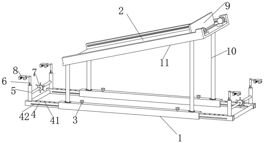
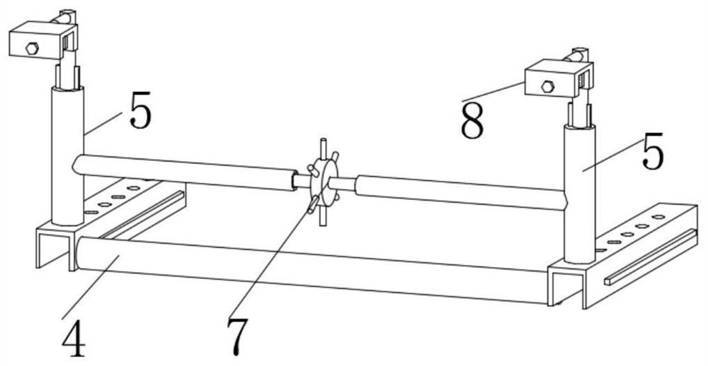
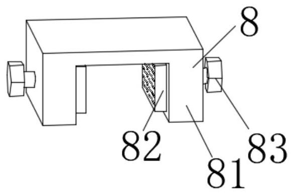
The invention discloses a high-efficiency solar cell panel and a mounting structure thereof. The high-efficiency solar cell panel comprises U-shaped rods, two sets of U-shaped rods are symmetrically arranged front and back, and supporting rods are symmetrically arranged on the two sets of U-shaped rods left and right; the upper ends of the four sets of supporting rods are fixedly connected with the lower end of an obliquely-arranged mounting plate in a threaded mode; U-shaped frames are slidably clamped in U-shaped cavities of the two sets of U-shaped rods correspondingly, T-shaped rods are symmetrically installed at the upper ends of the two sets of U-shaped frames front and back, lifting mechanisms are arranged in inner cavities of the four sets of T-shaped rods correspondingly, and clamping and fixing mechanisms are installed on the portions, located above the T-shaped rods, of the four sets of lifting mechanisms. According to the high-efficiency solar cell panel and the mounting structure thereof, the U-shaped frames, the T-shaped rods, the lifting mechanisms, the driving mechanisms and the clamping and fixing mechanism are arranged, installation of equipment can be achieved, punching is not needed, a scraper mechanism is arranged, dust or accumulated snow is prevented from influencing illumination of the solar cell panel, and the power generation efficiency of the solar cell panel is improved.

Description

technical field [0001] The invention relates to the field of solar power generation equipment, in particular to a high-efficiency solar battery panel and its installation structure. Background technique [0002] A solar panel is a device that directly or indirectly converts solar radiation into electrical energy through the photoelectric effect or photochemical effect by absorbing sunlight. The main material of most solar panels is "silicon". It is so large that its general use still has certain limitations. [0003] Existing, the existing household solar power generation equipment generally consists of solar panels and mounting brackets. It is fixed to the roof, and the drilling operation is easy to damage the structure of the house, and it is not convenient to remove the fixing frame from the roof after fixing. At the same time, when snow or dust accumulates on the solar panel, it will affect the power generation efficiency of the power generation panel. Therefore, , we ...

Claims


Application Information

Patent Timeline
Patent Type & Authority Applications(China)
IPC IPC(8): H02S20/30H02S40/10H02S40/12F24S25/61F24S25/634
CPCH02S20/30H02S40/10H02S40/12F24S25/61F24S25/634Y02E10/47Y02E10/50
Inventor 常春徐金涛赵龙
Owner 安徽联维新能源科技有限公司
Why Eureka
Try Eureka